
Page 247 - Reciprocating Compressors Operation Maintenance
P. 247
232 Reciprocating Compressors: Operation and Maintenance
of faulty equipment support, has been forced into a curve. At zero
degrees of rotation, the web opening A is less than ideal, while that at B
is greater than ideal. After rotating the crankshaft 180°, the condition is
reversed. Because the centerline is the same, the crankshaft must now
bend in the opposite direction. The A opening has now increased, while
B has decreased. This flexing of the crankshaft as it rotates represents
cyclic stresses that, if of sufficient magnitude, can lead to fatigue failure.
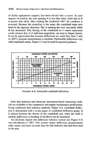
It can be appreciated that because deflections are small (less than 5 mils
or .005"), accurate measurement is essential. Permissible deflections vary
with crankshaft stroke. Figure 4-3 can be used for general guidance.
CRANKSHAFT STROKE, MILLIMETERS
0 100 200 300 400 600 600
^i .mi - - 128
r
- - - *rf" •«•*
1 REALIGNMENT _ ** i>P
REQUIRED +* •"•*
*>*
f*
ltjfi
**• -50 K
rf*
i *+ •(•* ALIGNMENT _
1 *»• <••' jdtf 0.K. — OK JH
n* *•*
**• - -
id**
(j : ii 5 1 1 1 0 1I 1 4 16 1) 20 2^ 2(
CRANKSHAFT STROKE, INCHES
FIGURE: 4-3. Permissible crankshaft deflections.
Both dial indicator and electronic instrument-based measuring meth-
ods are available to the compressor and engine maintenance professional.
Using traditional dial indicator methods, Figure 4-4, crankshaft deflec-
tion is determined with a strain gauge or crankshaft deflection gauge. It
is placed between the throws of the crankshaft and, when the shaft is
rotated, deflections or bending of the throw can be measured.
An electronic digital web deflection indicator system (see Figure 4-5)
was introduced in 1983. This system makes deflection measurements
safer, easier, and more accurate than the dial indicator that had been used
in the past.