
Page 83 - Reciprocating Compressors Operation Maintenance
P. 83
7O Reciprocating Compressors: Operation and Maintenance
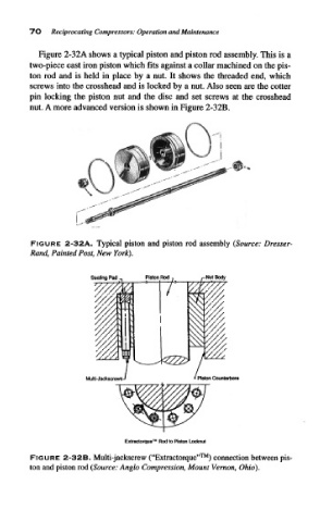
Figure 2-32A shows a typical piston and piston rod assembly. This is a
two-piece cast iron piston which fits against a collar machined on the pis-
ton rod and is held in place by a nut. It shows the threaded end, which
screws into the crosshead and is locked by a nut. Also seen are the cotter
pin locking the piston nut and the disc and set screws at the crosshead
nut, A more advanced version is shown in Figure 2-32B.
FIGURE 2-32A. Typical piston and piston rod assembly (Source: Dresser-
Rand, Painted Post, New York),
Seating Pad _ Piston Rod , r Nut Body
Multi-JackscrewsJ * Piston Counterbore
Extractorque™ Rod to Piston Lockout
FIGURE 2-32B. Multi-jackscrew ("Extractorque"™) connection between pis-
ton and piston rod (Source: Anglo Compression, Mount Vernon, Ohio).