
Page 184 - Renewable Energy Devices and System with Simulations in MATLAB and ANSYS
P. 184
Small Wind Energy Systems 171
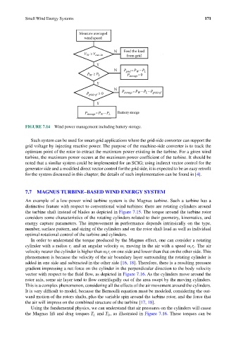
Measure averaged
wind speed
N Feed the load
V W ≥V cut–in from grid
Y
N P grid =P –P L
W
P W ≥ P L P storage =0
Y
N
P grid,ref ≥ 0 P storage =P – P – P grid,ref
L
W
Y
P storage =P –P L Battery storge
W
FIGURE 7.14 Wind power management including battery storage.
Such system can be used for smart-grid applications where the grid-side converter can support the
grid voltage by injecting reactive power. The purpose of the machine-side converter is to track the
optimum point of the rotor to extract the maximum power existing in the turbine. For a given wind
turbine, the maximum power occurs at the maximum power coefficient of the turbine. It should be
noted that a similar system could be implemented for an SCIG; using indirect vector control for the
generator side and a modified direct vector control for the grid side, it is expected to be an easy retrofit
for the system discussed in this chapter; the details of such implementation can be found in [4].
7.7 MAGNUS TURBINE–BASED WIND ENERGY SYSTEM
An example of a low-power wind turbine system is the Magnus turbine. Such a turbine has a
distinctive feature with respect to conventional wind turbines: there are rotating cylinders around
the turbine shaft instead of blades as depicted in Figure 7.15. The torque around the turbine rotor
considers some characteristics of the rotating cylinders related to their geometry, kinematics, and
energy capture parameters. The improvement in performance depends intrinsically on the type,
number, surface pattern, and sizing of the cylinders and on the rotor shaft load as well as individual
optimal rotational control of the turbine and cylinders.
In order to understand the torque produced by the Magnus effect, one can consider a rotating
cylinder with a radius r c and an angular velocity ω c moving in the air with a speed ω cc r . The air
velocity nearer the cylinder is higher than ω cc r on one side and lower than that on the other side. This
phenomenon is because the velocity of the air boundary layer surrounding the rotating cylinder is
added in one side and subtracted in the other side [16, 18]. Therefore, there is a resulting pressure
gradient impressing a net force on the cylinder in the perpendicular direction to the body velocity
vector with respect to the fluid flow, as depicted in Figure 7.16. As the cylinders move around the
rotor axis, some air layer tend to flow centrifugally out of the area swept by the moving cylinders.
This is a complex phenomenon, considering all the effects of the air movement around the cylinders.
It is very difficult to model, because the Bernoulli equation must be modeled, considering the out-
ward motion of the rotors shafts, plus the variable spin around the turbine rotor, and the force that
the air will impress on the combined structure of the turbine [17, 18].
Using the fundamental physics, we can understand that air pressures on the cylinders will cause
the Magnus lift and drag torques T L and T D , as illustrated in Figure 7.16. These torques can be