
Page 185 - Renewable Energy Devices and System with Simulations in MATLAB and ANSYS
P. 185
172 Renewable Energy Devices and Systems with Simulations in MATLAB and ANSYS ®
®
FIGURE 7.15 Magnus turbine with nonsmooth rotating cylinders. (Courtesy of CEESP-UFSM/IFSC,
Brazil.)
dL
α
ω c
v is the resulting air speed on the cylinder surface
Wind
d=2r t direction V
ω t
α
ω r
t t
dD
v
Wind orthogonal
direction
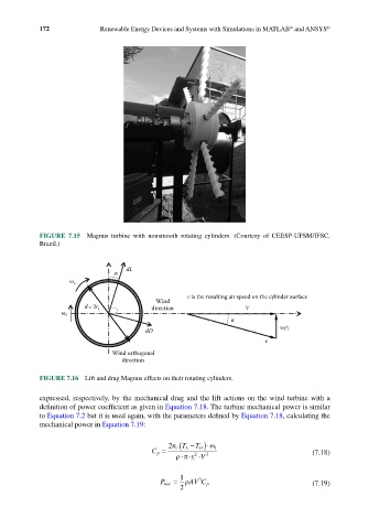
FIGURE 7.16 Lift and drag Magnus effects on their rotating cylinders.
expressed, respectively, by the mechanical drag and the lift actions on the wind turbine with a
definition of power coefficient as given in Equation 7.18. The turbine mechanical power is similar
to Equation 7.2 but it is used again, with the parameters defined by Equation 7.18, calculating the
mechanical power in Equation 7.19:
c (
2 nT L − )⋅ω t
T D
C p = 2 3 (7.18)
⋅
⋅⋅
ρπ rV
t
1
3
P mec = ρ AVC p (7.19)
2