
Page 180 - Renewable Energy Devices and System with Simulations in MATLAB and ANSYS
P. 180
Small Wind Energy Systems 167
Maximum power tracking
AC DC
Wind
generator
AC AC Grid
DC
DC
DC
FIGURE 7.11 Power electronic converter topology for small wind turbines with maximum power tracking.
Very good ventilation should be implemented in order to cool down the generator, particularly for
extremely compact applications.
The electrical generator is connected to a small-scale wind turbine, as indicated in Figure 7.11.
The wind turbine typically has fixed attack angles of the blades. Either the wind energy system is
connected to the distribution grid or supplies a DC load with power electronic interfaces. The con-
trol must be based on the wind acting on the turbine rotation and balance of the load power. The DC/
DC converter connected to the DC link can serve as a storage, or it is sometimes implemented as
an electrical braking for wind turbines, particularly for wind gusts or any runoff of the turbine that
might cause power imbalance with the load or the grid. As the rotor speed changes, according to the
wind speed, the speed control of the turbine should command low speed at low winds and high speed
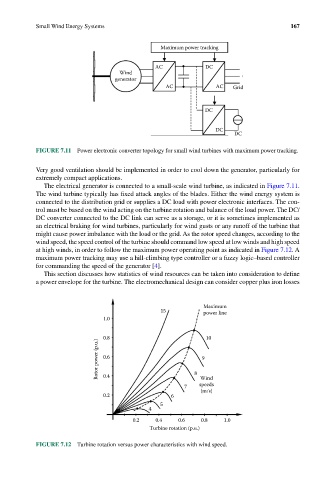
at high winds, in order to follow the maximum power operating point as indicated in Figure 7.12. A
maximum power tracking may use a hill-climbing type controller or a fuzzy logic–based controller
for commanding the speed of the generator [4].
This section discusses how statistics of wind resources can be taken into consideration to define
a power envelope for the turbine. The electromechanical design can consider copper plus iron losses
Maximum
15 power line
1.0
0.8 10
Rotor power (p.u.) 0.6 8 9
0.4
Wind
7 speeds
(m/s)
0.2 6
5
4
0.2 0.4 0.6 0.8 1.0
Turbine rotation (p.u.)
FIGURE 7.12 Turbine rotation versus power characteristics with wind speed.