Page 267 - Renewable Energy Devices and System with Simulations in MATLAB and ANSYS
P. 267

254             Renewable Energy Devices and Systems with Simulations in MATLAB  and ANSYS ®
                                                                                ®

                      ω , θ     J BI
                       BI   BI
                                   BI
                      T BI       d D HBI                 1:N
                                 K HBI   d HGB            GB GB
                                                            1
                                  D H    K HGB     D             J           D
                                                                              G
                         ω ,θ H                     GB            gb1       ω , θ
                          H
                        K                                                    G   G
                      d HB2 HB2  J H                                d GBG
                     J B2                T B3                       K GBG
                               K HB3         ω , θ   J gb2                 G
                                              B3   B3
                                                        , θ
                         D B2  d HB3  D B3  J        ω GB   GB   GB
                         ω , θ          B3                         2         J G  T e
                          B2   B2
                        T B2
                     (a)
                                                K 2M
                                                                  J'
                            J" WT                                  G
                                                 K
                                                                      T
                      T' WT                                            e
                     (b)

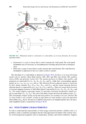
            FIGURE 10.2  Mechanical model of a drivetrain of a wind turbine: (a) six-mass drivetrain, (b) two-mass
            equivalent model.


              •  Anemometer is a type of sensor that is used to measure the wind speed. The wind speed
                 information may be necessary for maximum power tracking and protection in emergency
                 cases.
              •  Wind vane is a type of sensor that is used to measure the wind direction. The wind direction
                 information is important for the yaw control system to operate.

              The drivetrain of a wind turbine is depicted in Figure 10.2a. It shows a six-mass drivetrain
            model with six inertias: three blade inertias (JB1,  JB2, and  JB3), hub inertia (JH), gearbox
            inertia (JGB), and generator inertia (JG). The angular positions for blades, hub, gearbox, and
            generator are represented by θ , θ , θ , θ , θ , and θ , while their corresponding angular
                                      B1
                                             B3
                                          B2
                                                    GB
                                                 H
                                                            G
            speeds are ω , ω , ω , ω , ω , and ω . The elasticity between adjacent masses is expressed
                      B1
                              B3
                          B2
                                     GB
                                  H
                                             G
            by their spring constants K HB1 , K HB2 , K HB3 , K HGB , and K GBG  and the mutual damping between
            adjacent masses is expressed by d HB1 , d HB2 , d HB3 , d HGB , and d GBG . There are torque losses because
            of external damping elements of individual masses, represented by D , D , D , D , D , and
                                                                      B1
                                                                              B3
                                                                          B2
                                                                                  H
                                                                                     GB
            D . This model requires a generator torque (T ) and three individual aerodynamic torques act-
             G
                                                  E
            ing on each blade (T , T , T ). The sum of the blade torques develops the turbine torque, T .
                             B1
                                    B3
                                B2
                                                                                         WT
            The aerodynamic torques acting on the hub and gearbox are assumed to be zero. Because the
            six-mass model is very complex, usually an equivalent two-mass model is used with equivalent
            shaft stiffness K , that is, the masses of turbine and gearbox are lumped together into one mass,
                         2M
            such simplified model is represented in Figure 10.2b.
            10.3  WIND TURBINE CHARACTERISTICS
            In order to understand the characteristics of wind energy conversion and how a turbine works, it is
            possible to make a simplified assumption that the wind approaches the turbine with constant veloc-
            ity, with homogeneous properties (such as temperature, density), and without turbulence. Suppose
   262   263   264   265   266   267   268   269   270   271   272