
Page 268 - Renewable Energy Devices and System with Simulations in MATLAB and ANSYS
P. 268
Design Considerations for Wind Turbine Systems 255
1 2
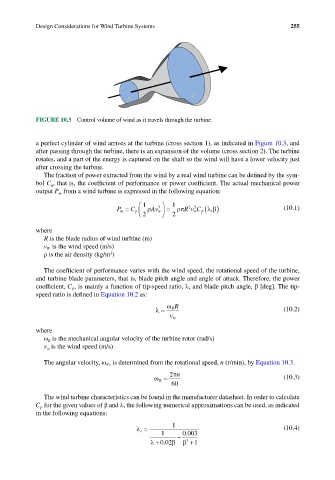
FIGURE 10.3 Control volume of wind as it travels through the turbine.
a perfect cylinder of wind arrives at the turbine (cross section 1), as indicated in Figure 10.3, and
after passing through the turbine, there is an expansion of the volume (cross section 2). The turbine
rotates, and a part of the energy is captured on the shaft so the wind will have a lower velocity just
after crossing the turbine.
The fraction of power extracted from the wind by a real wind turbine can be defined by the sym-
bol C , that is, the coefficient of performance or power coefficient. The actual mechanical power
p
output P from a wind turbine is expressed in the following equation:
m
1 1
2 3
3
P m = C p ρ Av w = ρπ Rv C p (λ β ) (10.1)
,
w
2 2
where
R is the blade radius of wind turbine (m)
v W is the wind speed (m/s)
3
ρ is the air density (kg/m )
The coefficient of performance varies with the wind speed, the rotational speed of the turbine,
and turbine blade parameters, that is, blade pitch angle and angle of attack. Therefore, the power
coefficient, C p , is mainly a function of tip-speed ratio, λ, and blade pitch angle, β [deg]. The tip-
speed ratio is defined in Equation 10.2 as:
ω R R
λ = (10.2)
w v
where
ω is the mechanical angular velocity of the turbine rotor (rad/s)
R
v is the wind speed (m/s)
w
The angular velocity, ω R , is determined from the rotational speed, n (r/min), by Equation 10.3.
2 πn
ω R = (10.3)
60
The wind turbine characteristics can be found in the manufacturer datasheet. In order to calculate
C p for the given values of β and λ, the following numerical approximations can be used, as indicated
in the following equations:
1
λ i = (10.4)
1 − 0 003
.
3
λ + 002. β β +1