
Page 266 - Renewable Energy Devices and System with Simulations in MATLAB and ANSYS
P. 266
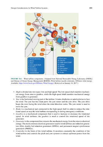
Design Considerations for Wind Turbine Systems                              253


                                       3


                                                 4
                             2
                                                       5
                                                             6           8
                                1
                                                                 7
                                       16


                                         15

                                                                        9
                                          14
                                                              11        10
                                 13      12
                             1. Wind direction           9. Wind vane
                             2. Rotor                    10. Nacelle
                             3. Pitch                    11. High-speed shaft
                             4. Low-speed shaft          12. Tower
                             5. Gearbox                  13. Blades
                             6. Generator                14. Yaw motor
                             7. Controller               15. Yaw drive
                            8. Anemometer                16. Brake


            FIGURE 10.1  Wind turbine components. (Adapted from National Renewable Energy Laboratory [NREL]
            and Bureau of Ocean Energy Management [BOEM], Wind turbine nacelle schematic, Offshore wind energy,
            Available: https://www.boem.gov/Offshore-Wind-Energy/, Retrieved on January 18, 2017.)


              •  Shaft is divided into two types: low and high speed. The low-speed shaft transfers mechani-
                 cal energy from rotor to gearbox, while the high-speed shaft transfers mechanical energy
                 from gearbox to generator.
              •  Yaw is the horizontal moving part of the turbine. It turns clockwise or anticlockwise to face
                 the wind. The yaw has two main parts: the yaw motor and the yaw drive. The yaw drive
                 keeps the rotor facing the wind when the wind direction varies. The yaw motor is used to
                 move the yaw.
              •  Brake is a mechanical part connected to the high-speed shaft in order to reduce the rota-
                 tional speed or stop the wind turbine overspeeding or during emergency conditions.
              •  Gearbox is a mechanical component that is used to increase or decrease the rotational
                 speed. In wind turbines, the gearbox is used to control the rotational speed of the
                 generator.
              •  Generator is the component that converts the mechanical energy from the rotor to electrical
                 energy. The most common electrical generators used in wind turbines are induction genera-
                 tors (IGs), doubly fed induction generators (DFIGs), and permanent magnet synchronous
                 generators (PMSGs).
              •  Controller is the brain of the wind turbine. It monitors constantly the condition of the
                 wind turbine and controls the pitch and yaw systems to extract optimum power from the
                 wind.