
Page 276 - Renewable Energy Devices and System with Simulations in MATLAB and ANSYS
P. 276
Design Considerations for Wind Turbine Systems 263
(between generated power, P , and reference power, P ) is processed through a controller. Most
ref
gen
of the time a simple PI controller is used and P is considered as the rated power from the genera-
ref
tor. The pitch servo is modeled with a first-order delay system with a time constant, T . As the pitch
d
actuation system, in general, cannot respond instantly, a rate limiter is added to obtain a realistic
response. Finally, a hard limiter is also added so that the pitch angle, β, is not capable of exceeding
the design limit of the pitch system.
10.6.2 Electrical Control
From a control point of view, the permanent magnet machine as discussed in Chapter 7 supports
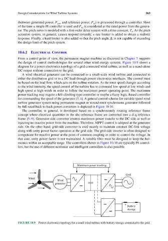
the design of control methodologies for several other wind energy systems. Figure 10.9 shows a
diagram for a power electronics topology of a grid-connected wind turbine, as well as a stand-alone
DC output without connection to the grid.
A wind electrical generator can be connected to a small-scale wind turbine and connected to
either the distribution grid or to a DC load through power electronics interfaces. The control must
be based on the load flow, which acts on the turbine rotation. As the rotor speed changes according
to the wind intensity, the speed control of the turbine has to command low speed at low winds and
high speed at high winds in order to follow the maximum power operating point. The maximum
power tracking may require a hill-climbing type controller or maybe a fuzzy logic–based controller
for commanding the speed of the generator [3, 4]. A general control scheme for variable speed wind
turbine generator system using permanent magnet or wound rotor synchronous generator followed
by full-rated back-to-back power converters is depicted in Figure 10.10.
The controller, in general, is developed based on a synchronously rotating reference frame
concept where electrical quantities in the abc-reference frame are converted into a d–q reference
frame [5–9]. Generator-side converter ensures maximum power transfer to the DC side as well as
injecting no reactive power from the machine. Therefore, MPPT control is adopted at the generator
side. On the other hand, grid-side converter is used mainly to maintain constant DC-link voltage
along with unity power factor operation at the grid side. The grid-side inverter is often designed to
compensate for reactive power at the point of common coupling in order to control the voltage. In
that case, unity power factor is not maintained. A suitable filter must be designed to keep the har-
monics within an acceptable range. The controllers shown in Figure 10.10 are typically PI control-
lers, but the use of different nonlinear and intelligent controllers is also possible.
Maximum power tracking
Grid
Wind
Wind
generator
+ –
Battery
storage
FIGURE 10.9 Power electronics topology for a small wind turbine with battery storage connected to the grid.