
Page 297 - Renewable Energy Devices and System with Simulations in MATLAB and ANSYS
P. 297
284 Renewable Energy Devices and Systems with Simulations in MATLAB and ANSYS ®
®
100 Averaged electrical power (kW) 100
Capacity factor (%) =280.5 (kW) 80
Averaged electrical power (kW) 60 factor (C ) f ae P rated (C f = 30%) C =30% 60 Capacity factor (%)
80
P =84.2 (kW) with P
ae
rated
Averaged electrical
power (P )
= 280.5 (kW)
Capacity
40
40
f
20
0
0 20
0 100 200 300 400 500 600
Rated power (kW)
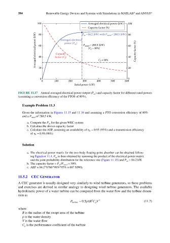
FIGURE 11.17 Annual averaged electrical power output (P ae ) and capacity factor for different rated powers
(assuming a conversion efficiency of the PTOS of 80%).
Example Problem 11.3
Given the information in Figures 11.15 and 11.16 and assuming a PTO conversion efficiency of 80%
and a P rated of 280.5 kW,
a. Compute the P ae for the given WEC system
b. Calculate the device capacity factor
.
c. Calculate the AEP, assuming an availability of η 2 = 095 (95%) and a transmission efficiency
of η 3 = 098 (98%)
.
Solution
a. The electrical power matrix for the two-body floating-point absorber can be obtained follow-
ing Equation 11.4. P ae is then obtained by summing the product of the electrical power matrix
and the joint probability distribution for the reference site (Figure 11.15) and P ae = 84.2 kW.
b. The capacity factor = P ae /P rated = 30%.
c. AEP = 84.2*8766*98%*95% = 687 MWh.
11.5.2 CEC Generator
A CEC generator is usually designed very similarly to wind turbine generators, so these problems
and exercises are derived in similar analogy to designing wind turbine generators. The available
hydrokinetic power of a water turbine can be computed from the water flow and the turbine dimen-
sion as
2
P turb nei = 0.5ρπ R CV 3 (11.7)
p
where
R is the radius of the swept area of the turbine
ρ is the water density
V is the water flow
C is the performance coefficient of the turbine
p