
Page 300 - Renewable Energy Devices and System with Simulations in MATLAB and ANSYS
P. 300
Marine and Hydrokinetic Power Generation and Power Plants 287
Output power (kW) and rotational speed (rpm)
2000 50
1800 P (kW)-C pmax 45
1600 wr (rpm) 40
1400 35
1200 30
1000 25
800 20
600 15
400 10
200 5
0 0
0 1 2 3 4 5
Water flow (m/s)
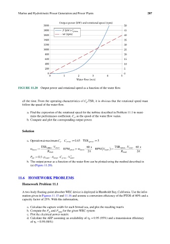
FIGURE 11.20 Output power and rotational speed as a function of the water flow.
all the time. From the operating characteristics of C p -TSR, it is obvious that the rotational speed must
follow the speed of the water flow.
a. Find the expression of the rotational speed for the turbine described in Problem 11.1 to maxi-
mize the performance coefficient, C p , as the speed of the water flow varies.
b. Compute and plot the corresponding output power.
Solution
.
a. OperationatmaximumC p C pmax := 045 TSR cpmax := 5
V ⋅ 60 s V ⋅ water 60 s
ω speed := TSR cpmax water RPM speed := ω speed ⋅ RPM( V wateer) =: TSR cpmax ⋅
R blade 2 π R blade 2π
. ⋅
3
P out := 05 ρ water ⋅ A swept ⋅ C pmax ⋅ V water
b. The output power as a function of the water flow can be plotted using the method described in
(a) (Figure 11.20).
11.6 HOMEWORK PROBLEMS
Homework Problem 11.1
A two-body floating-point absorber WEC device is deployed in Humboldt Bay, California. Use the infor-
mation given in Figures 11.15 and 11.16 and assume a conversion efficiency of the PTOS of 80% and a
capacity factor of 25%. With this information,
a. Calculate the capture width for each binned sea, and plot the resulting matrix
b. Compute the P ae and P rated for the given WEC system
c. Plot the electrical power matrix
.
d. Calculate the AEP assuming an availability of η 2 = 095 (95%) and a transmission efficiency
of η 3 = 098 (98%)
.