
Page 305 - Renewable Energy Devices and System with Simulations in MATLAB and ANSYS
P. 305
292 Renewable Energy Devices and Systems with Simulations in MATLAB and ANSYS ®
®
12.1 FUEL CELL TYPES AND OPERATION
Fuel cells are modular, environmentally clean, sustainable, efficient, and of a versatile technology.
Fuel cell systems have been demonstrated for clean energy, transportation, and various other appli-
cations. A fuel cell is a device that generates electricity by a chemical reaction. It has two electrodes,
an anode and a cathode, with an electrolyte sandwiched between them. Hydrogen is the basic fuel
for fuel cells, and exposing the anode to hydrogen and the cathode to oxygen derived from air
results in electricity being produced without combustion of any form. Water and heat are the only
by-products when pure hydrogen is used as the fuel source. Although hydrogen is considered the
primary fuel source for fuel cells, the process of fuel reforming allows for the extraction of hydrogen
from other fuels including methanol, natural gas, petroleum, or renewable hydrocarbon sources.
The first fuel cell was developed in 1839 by Sir William Grove, a Welsh judge and a scientist [1].
Fuel cells are generally classified according to the nature of the electrolyte, each type requiring a
particular type of electrolyte material. Also, each fuel cell type has its own unique characteristics
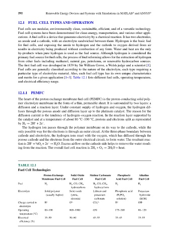
and merits for a given application [1–3]. Table 12.1 lists different fuel cells, operating temperature,
and electrical efficiency range.
12.1.1 PEMFC
The heart of the proton exchange membrane fuel cell (PEMFC) is the proton-conducting solid poly-
mer electrolyte membrane in the form of a thin, permeable sheet. It is surrounded by two layers: a
diffusion and a reaction layer. Under constant supply of hydrogen and oxygen, the hydrogen dif-
fuses through the porous anode and diffusion layer up to the platinum catalyst. The reason for the
diffusion current is the tendency of hydrogen–oxygen reaction. In the reaction layer supported by
the catalyst and at a temperature of about 80 °C–100 °C, protons and electrons split as represented
+
−
by H → 2H + 2e .
2
The hydrogen ion passes through the polymer membrane on its way to the cathode, while the
only possible way for the electrons is through an outer circuit. At the three-phase boundary between
cathode and electrolyte, the hydrogen ions react with the oxygen, which has diffused through the
porous cathode and the electrons from the outer electrical circuit, to form water. The resultant reac-
−
+
tion is 2H + ½O + 2e → H O. Excess airflow on the cathode side helps to remove the water result-
2
2
ing from the reaction. The overall fuel cell reaction is 2H + O → 2H O + heat.
2
2
2
TABLE 12.1
Fuel Cell Technologies
Proton Exchange Solid Oxide Molten Carbonate Phosphoric Alkaline
Membrane Fuel Cell Fuel Cell Fuel Cell Acid Fuel Cell Fuel Cell
Fuel H 2 H 2 , CO, CH 4 , H 2 , CO, CH 4 , H 2 H 2
hydrocarbons hydrocarbons
Electrolyte Solid polymer Solid oxide Lithium and Phosphoric acid Potassium
(usually Nafion) (yttria, potassium (H 3 PO 4 hydroxide
zirconia) carbonate solution) (KOH)
Charge carried in H + O 2− CO 3 2− H + OH −
electrolyte
Operating 80–100 800–1000 650 175–200 80–120
temperature (°C)
Electrical 35–50 50–60 45–55 35–45 35–55
efficiency (%)