
Page 309 - Renewable Energy Devices and System with Simulations in MATLAB and ANSYS
P. 309
296 Renewable Energy Devices and Systems with Simulations in MATLAB and ANSYS ®
®
1.0 0.7
0.9 0.6 0.6
0.8
0.7 0.5 0.5
Voltage (V) 0.6 0.4 Efficiency P (W/cm 2 ) 0.4
0.5
0.3
0.3
0.4
0.3 0.2 0.2
0.2
0.1 0.1 0.1
0 0.0 0.0
0 0.5 1.0 1.5 0.0 0.5 1.0 1.5
2
2
(a) J (A/cm ) (b) J (A/cm )
0.7
1.0 0.6
0.6
0.8 0.5
0.5 0.4
Efficiency 0.4 0.6 Voltage (V) Thermal efficiency 0.3
0.3
0.4
0.2 0.2
0.2 PEM system
0.1 0.1 ICE
0.0 0.0 0
0.0 0.2 0.4 0.6 0 25 50 75
(c) P (W/cm ) (d) Load (%)
2
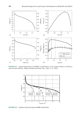
FIGURE 12.2 Typical characteristics of a PEMFC: (a) performance curve, (b) power density, (c) efficiency,
and (d) system efficiency. (Based on Kartha and Grimes, Phys. Today, 11, 54, 1994.)
1.2
1.0
0.8
Voltage (V) 0.6
0.4
Fuel cell Fuel cell Fuel cell Fuel cell
25% flow 50% flow 75% flow 100% flow
0.2
0 2 4 6 8 10
Current (A)
FIGURE 12.3 Variation of fuel cell output and MPP with fuel flow.