
Page 310 - Renewable Energy Devices and System with Simulations in MATLAB and ANSYS
P. 310
Power Conversion and Control for Fuel Cell Systems in Transportation 297
100%
80%
60%
40%
20% Maximum allowable H utilization (%)
2
Stack efficiency (%)
0%
0 20 40 60 80 100
Peak current ripple (%)
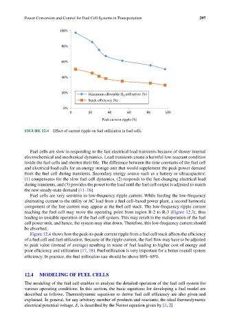
FIGURE 12.4 Effect of current ripple on fuel utilization in fuel cells.
Fuel cells are slow in responding to the fast electrical load transients because of slower internal
electrochemical and mechanical dynamics. Load transients create a harmful low-reactant condition
inside the fuel cells and shorten their life. The difference between the time constants of the fuel cell
and electrical load calls for an energy storage unit that would supplement the peak power demand
from the fuel cell during transients. Secondary energy source such as a battery or ultracapacitor:
(1) compensates for the slow fuel cell dynamics, (2) responds to the fast-changing electrical load
during transients, and (3) provides the power to the load until the fuel cell output is adjusted to match
the new steady-state demand [11–16].
Fuel cells are very sensitive to low-frequency ripple current. While feeding the low-frequency
alternating current to the utility or AC load from a fuel cell–based power plant, a second harmonic
component of the line current may appear at the fuel cell stack. The low-frequency ripple current
reaching the fuel cell may move the operating point from region R-2 to R-3 (Figure 12.3), thus
leading to unstable operation of the fuel cell system. This may result in the maloperation of the fuel
cell power unit, and hence, the system may shut down. Therefore, this low-frequency current should
be absorbed.
Figure 12.4 shows how the peak-to-peak current ripple from a fuel cell stack affects the efficiency
of a fuel cell and fuel utilization. Because of the ripple current, the fuel flow may have to be adjusted
to peak value (instead of average) resulting in waste of fuel leading to higher cost of energy and
poor efficiency and utilization [17, 18]. Fuel utilization is very important for a better overall system
efficiency. In practice, the fuel utilization rate should be above 80%–85%.
12.4 MODELING OF FUEL CELLS
The modeling of the fuel cell enables to analyze the detailed operation of the fuel cell system for
various operating conditions. In this section, the basic equations for developing a fuel model are
described as follows. Thermodynamic equations to derive fuel cell efficiency are also given and
explained. In general, for any arbitrary number of products and reactants, the ideal thermodynamic
electrical potential voltage, E, is described by the Nernst equation given by [1, 2]