
Page 315 - Renewable Energy Devices and System with Simulations in MATLAB and ANSYS
P. 315
302 Renewable Energy Devices and Systems with Simulations in MATLAB and ANSYS ®
®
magnet motors with Honda focusing on the concentrated winding–type and Toyota on distributed
winding–type motors [24]. The permanent magnet AC motor offers merits of higher power density
and thus lower weight compared to other types of motors of similar rating. Tesla is the only major
EV manufacturer using induction motors for propulsion. Induction motors were employed for most
of the early EVs including GM EV1 and FCVs [24]. Induction motors are rugged, have high-speed
capability, and are of a smaller size compared to a separately excited DC motor.
A power electronics system forms a major portion of the FCV propulsion system. It consists of a
power conditioner or a DC–DC converter to match the output voltage of the fuel cell stack to the DC
input voltage of the inverter. The inverter converts the DC voltage to the required voltage and fre-
quency to drive the propulsion motor. Also, additional power converters are required for powering
the balance of plant electrical loads of the fuel cell system and all the accessory loads of the vehicle.
Several requirements related to power converter and propulsion motor control strategies are similar
among the electric, hybrid, and fuel cell vehicles.
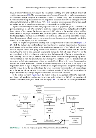
A fuel cell propulsion system with a battery pack and a power conditioner is shown in Figure 12.7
[7]. Both the fuel cell stack and the battery provide the power required for propulsion. The power
conditioner must be sized depending on the maximum power capacity of the fuel cell stack. To pre-
vent the negative current from going into the stack, a diode is connected in series with the fuel cell
stack. Negative current may cause cell reversal and damage the fuel cell stack. The power for the
accessory loads of the fuel cell system is derived from the battery side of the converter to make sure
that accessory loads are always powered even when the fuel cell stack is not producing any power.
This would help to start the system faster. The battery power could also be used to initially warm up
the system and bring the stack output voltage to a nominal level. Thus, in this kind of layout, starting
the fuel cell system will not be a concern. The battery voltage has to be selected to be equal to the
required DC input voltage to the power inverter. If the propulsion system is designed to be operated
at a DC voltage above the fuel cell voltage, the power conditioner boosts the fuel cell stack voltage
up to the battery voltage and also charges the propulsion batteries. If the fuel cell stack voltage is
higher than the battery voltage, the power conditioner acts as a buck converter.
In the system shown in Figure 12.8, the battery voltage is independent of the DC input volt-
age. Hence, a lower battery voltage can be selected and a bidirectional DC–DC converter is used
to match the battery voltage to the DC-link voltage [7–19]. The fuel cell stack voltage determines
Fuel cell
plant
accessory
loads
Hydrogen Power
Fuel cell conditioner Propulsion
unit CAP CAP
Air or DC-DC inverter
converter
Battery
Air input H input
2
control control
PWM logic Propulsion
and motor
Fuel cell gate drive
controller
Stack PI control + I ref Propulsion
system
current I fc _ controller
FIGURE 12.7 A fuel cell propulsion system with a power conditioner and battery.