
Page 320 - Renewable Energy Devices and System with Simulations in MATLAB and ANSYS
P. 320
Power Conversion and Control for Fuel Cell Systems in Transportation 307
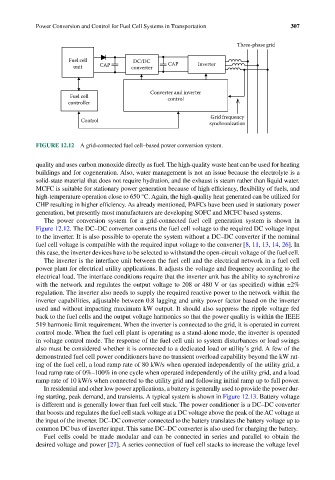
Three-phase grid
Fuel cell DC/DC
unit CAP converter CAP Inverter
Converter and inverter
Fuel cell control
controller
Grid frequency
Control
synchronization
FIGURE 12.12 A grid-connected fuel cell–based power conversion system.
quality and uses carbon monoxide directly as fuel. The high-quality waste heat can be used for heating
buildings and for cogeneration. Also, water management is not an issue because the electrolyte is a
solid-state material that does not require hydration, and the exhaust is steam rather than liquid water.
MCFC is suitable for stationary power generation because of high efficiency, flexibility of fuels, and
high-temperature operation close to 650 °C. Again, the high-quality heat generated can be utilized for
CHP resulting in higher efficiency. As already mentioned, PAFCs have been used in stationary power
generation, but presently most manufacturers are developing SOFC and MCFC based systems.
The power conversion system for a grid-connected fuel cell generation system is shown in
Figure 12.12. The DC–DC converter converts the fuel cell voltage to the required DC voltage input
to the inverter. It is also possible to operate the system without a DC–DC converter if the nominal
fuel cell voltage is compatible with the required input voltage to the converter [8, 11, 13, 14, 26]. In
this case, the inverter devices have to be selected to withstand the open-circuit voltage of the fuel cell.
The inverter is the interface unit between the fuel cell and the electrical network in a fuel cell
power plant for electrical utility applications. It adjusts the voltage and frequency according to the
electrical load. The interface conditions require that the inverter unit has the ability to synchronize
with the network and regulates the output voltage to 208 or 480 V or (as specified) within ±2%
regulation. The inverter also needs to supply the required reactive power to the network within the
inverter capabilities, adjustable between 0.8 lagging and unity power factor based on the inverter
used and without impacting maximum kW output. It should also suppress the ripple voltage fed
back to the fuel cells and the output voltage harmonics so that the power quality is within the IEEE
519 harmonic limit requirement. When the inverter is connected to the grid, it is operated in current
control mode. When the fuel cell plant is operating as a stand-alone mode, the inverter is operated
in voltage control mode. The response of the fuel cell unit to system disturbances or load swings
also must be considered whether it is connected to a dedicated load or utility’s grid. A few of the
demonstrated fuel cell power conditioners have no transient overload capability beyond the kW rat-
ing of the fuel cell, a load ramp rate of 80 kW/s when operated independently of the utility grid, a
load ramp rate of 0%–100% in one cycle when operated independently of the utility grid, and a load
ramp rate of 10 kW/s when connected to the utility grid and following initial ramp up to full power.
In residential and other low power applications, a battery is generally used to provide the power dur-
ing starting, peak demand, and transients. A typical system is shown in Figure 12.13. Battery voltage
is different and is generally lower than fuel cell stack. The power conditioner is a DC–DC converter
that boosts and regulates the fuel cell stack voltage at a DC voltage above the peak of the AC voltage at
the input of the inverter. DC–DC converter connected to the battery translates the battery voltage up to
common DC bus of inverter input. This same DC–DC converter is also used for charging the battery.
Fuel cells could be made modular and can be connected in series and parallel to obtain the
desired voltage and power [27]. A series connection of fuel cell stacks to increase the voltage level