
Page 319 - Renewable Energy Devices and System with Simulations in MATLAB and ANSYS
P. 319
306 Renewable Energy Devices and Systems with Simulations in MATLAB and ANSYS ®
®
systems can be used to produce power to meet the local demands, provide surplus power to the grid
in a net-metered or electricity buyback scenario, and also provide buffering and additional power for
grid-independent systems that rely on intermittent renewables. The hydrogen required for fuel cells
can be produced from natural gas; liquid hydrocarbon fuels including biomass fuels, landfill gases,
water, and electricity (via the process of electrolysis); biological processes including those involving
algae; and gasification of biomass, wastes, and coal. Because fuel cells have no moving parts and do
not involve combustion, they can operate reliably for a long period of time.
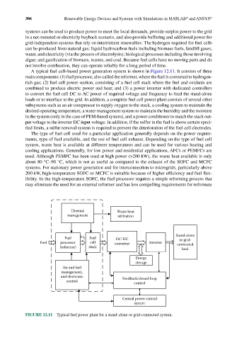
A typical fuel cell–based power generation system is shown in Figure 12.11. It consists of three
main components: (1) fuel processor, also called the reformer, where the fuel is converted to hydrogen-
rich gas; (2) fuel cell power section, consisting of a fuel cell stack where the fuel and oxidants are
combined to produce electric power and heat; and (3) a power inverter with dedicated controllers
to convert the fuel cell DC to AC power of required voltage and frequency to feed the stand-alone
loads or to interface to the grid. In addition, a complete fuel cell power plant consists of several other
subsystems such as an air compressor to supply oxygen to the stack, a cooling system to maintain the
desired operating temperature, a water management system to maintain the humidity and the moisture
in the system (only in the case of PEM-based system), and a power conditioner to match the stack out-
put voltage to the inverter DC input voltage. In addition, if the sulfur in the fuel is above certain speci-
fied limits, a sulfur removal system is required to prevent the deterioration of the fuel cell electrodes.
The type of fuel cell used for a particular application generally depends on the power require-
ments, type of fuel available, and the use of fuel cell exhaust. Depending on the type of fuel cell
system, waste heat is available at different temperatures and can be used for various heating and
cooling applications. Generally, for low power and residential applications, AFCs or PEMFCs are
used. Although PEMFC has been used at high power (>200 kW), the waste heat available is only
about 80 °C–90 °C, which is not as useful as compared to the exhaust of the SOFC and MCFC
systems. For stationary power generation and for interconnection to microgrids, particularly above
200 kW, high-temperature SOFC or MCFC is suitable because of higher efficiency and fuel flex-
ibility. In the high-temperature SOFC, the fuel processor requires a simple reforming process that
may eliminate the need for an external reformer and has less compelling requirements for reformate
Thermal Waste heat
management utilization
Fuel H 2 Fuel DC-DC Stand-alone
or grid-
Fuel processor cell converter Inverter connected
(reformer) stack load
Energy
storage
Air and fuel
management,
and electronic Feedback/closed-loop
control control
Central power control
system
FIGURE 12.11 Typical fuel power plant for a stand-alone or grid-connected system.