
Page 322 - Renewable Energy Devices and System with Simulations in MATLAB and ANSYS
P. 322
Power Conversion and Control for Fuel Cell Systems in Transportation 309
SOFC DC/DC
fuel cell converter V do C d
Heat
Three-phase
Microturbine output
generator
FIGURE 12.16 Power conversion systems for combining SOFC and turbine generator outputs.
could be provided by either system operating alone [1, 26]. In this type of hybrid power generation
system, the high-temperature exhaust of SOFC unit can be used to run the turbine generator. The
output of the turbine generator and the fuel cell output can be combined as shown in Figure 12.16
[28]. Fuel cell DC–DC converter and the AC to DC PWM rectifier at the output of the turbine gen-
erator must be controlled to share the output power according to their VA ratings and regulate the
DC-link voltage of the inverter. In a hybrid system, the microturbine generator functions as a turbo
charger for the SOFC, resulting in system efficiencies greater than 65%. Fuel cell power units and
also hybrid power generation systems can be combined with other power generation sources in a
microgrid to feed power to DC- and AC-type loads [29].
12.7 POWER ELECTRONICS FOR FUEL CELL APPLICATIONS
Power electronics is an essential component in a fuel cell power conversion system to convert vari-
able fuel cell stack DC voltage into regulated output DC voltage or desired AC voltage and fre-
quency. In fuel cell inverter applications, the fuel cell stack voltage must first be boosted to at least
the peak of the utility line AC voltage at the DC link of the inverter. This DC–AC power conversion
is possible using single-stage or multistage power conversion. Depending on fuel cell stack voltage,
particularly at lower voltages, a transformer-isolated DC–DC power converter is necessary to be
used as a boost converter. Also, the transformer isolates fuel cell stack from the utility line in case of
fault and also ensures the safety of personnel.
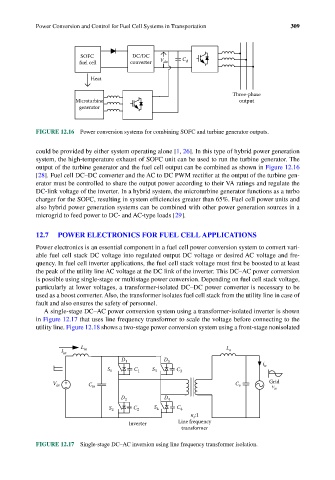
A single-stage DC–AC power conversion system using a transformer-isolated inverter is shown
in Figure 12.17 that uses line frequency transformer to scale the voltage before connecting to the
utility line. Figure 12.18 shows a two-stage power conversion system using a front-stage nonisolated
L in L
I in o
D 1 D 3 i
S 1 C 1 S 3 C 3 u
V in + C in C o Grid
v
–
u
D 2 D 4
S 2 C 2 S 4 C 4
n :1
t
Inverter Line frequency
transformer
FIGURE 12.17 Single-stage DC–AC inversion using line frequency transformer isolation.