
Page 321 - Renewable Energy Devices and System with Simulations in MATLAB and ANSYS
P. 321
308 Renewable Energy Devices and Systems with Simulations in MATLAB and ANSYS ®
®
DC/DC
Battery
converter
120 V/ 240 V
Fuel cell CAP DC/DC CAP Inverter one-phase
unit converter output
Converter Inverter
control
Fuel cell control
controller
Control
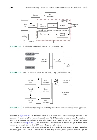
FIGURE 12.13 A stand-alone low power fuel cell power generation system.
Fuel cell unit
Fuel cell unit
DC–DC Three-phase
converter inverter
Three-phase
output
Fuel cell unit
FIGURE 12.14 Modular series-connected fuel cell units for high power application.
Fuel cell Boost Three-phase
unit converter inverter
Battery
Fuel cell Boost
unit converter
Three-phase
output
Fuel cell Boost
unit converter
FIGURE 12.15 A modular fuel power system with independent boost converters for high power application.
is shown in Figure 12.14. The fuel flow in all fuel cell units should be the same to produce the same
amount of current to achieve optimal operation. A DC–DC converter is used to meet the input volt-
age requirement of a three-phase inverter. This configuration needs only a single DC–DC converter
and one inverter. In Figure 12.15, the fuel cell stacks are connected in parallel using individual boost
converters to obtain the required DC input voltage to the inverter.
High-temperature fuel cell–based systems could be combined with another power generation
technology such as a turbine or a microturbine resulting in higher power generation efficiency than