
Page 323 - Renewable Energy Devices and System with Simulations in MATLAB and ANSYS
P. 323
310 Renewable Energy Devices and Systems with Simulations in MATLAB and ANSYS ®
®
L L
I in in o
D D 3
D b 1 i u
S 1 C 1 S 3 C 3
D sb
+
V in – S b C sb C C o Grid
v
d
D 2 D 4 u
S 2 C 2 S 4 C 4
n t :1
Inverter Line frequency
Nonisolated boost transformer
converter (DC-DC)
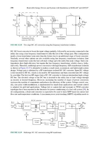
FIGURE 12.18 Two-stage DC–AC conversion using line frequency transformer isolation.
DC–DC boost converter to boost the input voltage partially, followed by an inverter connected to the
utility line using a line frequency transformer to offer the rest of the voltage gain. This configuration
needs a lower transformer turns ratio than the former due to an additional stage of boost converter.
Similarly, several other options are also available using line frequency transformer isolation. Line
frequency transformer scales the fuel cell stack voltage up to the utility line peak voltage. Such con-
figurations show high efficiency but require the line frequency transformer, which is heavy, bulky,
and costly. Therefore, multistage power conversion with high-frequency (HF) transformer isolation
as shown in Figure 12.19 is desirable to realize a small-sized, economical, and lightweight system
design. Voltage gain is obtained by a HF transformer-isolated DC–DC converter. Input DC voltage
is first inverted to HF AC, which is elevated by HF transformer and then converted into DC voltage
by a rectifier. The first two HF stages form a DC–DC converter to form an intermediate high-voltage
DC bus. The elevated voltage of the DC bus is inverted to the utility line or load voltage through
an inverter at desired frequency. However, increasing the number of stages of power conversion
increases the number of components and reduces the efficiency of the system. Voltage control, usu-
ally, sine pulse width modulation, is implemented for stand-alone applications and current control
is adopted for grid-tied applications. Voltage-fed or current-fed and resonant or PWM converter
topologies have been reported in the literature for power conditioning of a fuel cell system [29]. In
all configurations, a front-end converter is expected to be used to track MPP based on current fuel
flow rate and temperature conditions. A maximum power point tracking (MPPT) algorithm needs to
DC/DC converter
L in L d L o L
Fuel + DC-AC AC-DC + v u
cell – C in C d V DC DC-AC C o v inv v L
– Grid
HF i u
transformer HF Intermediate
HF rectifier DC link HF voltage
inverter controlled
PWM VSI
+
Control –
circuit +
Reference Control –
voltage circuit Reference
signal (V or I)
(Line frequency)
FIGURE 12.19 Multistage DC–AC conversion using HF transformer.