
Page 316 - Renewable Energy Devices and System with Simulations in MATLAB and ANSYS
P. 316
Power Conversion and Control for Fuel Cell Systems in Transportation 303
Accessory
loads
Hydrogen
Fuel cell CAP Propulsion
unit inverter
Air
Air input H input DC-DC
2
control control converter
Control
Fuel cell
controller Battery Propulsion
motor
Vm I Total
– Propulsion
I fc I ref
PI control system
+ Power controller
command
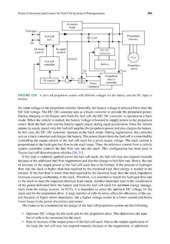
FIGURE 12.8 A fuel cell propulsion system with different voltages for the battery and the DC input to
inverter.
the input voltage to the propulsion inverter. Generally, the battery voltage is selected lower than the
DC-link voltage. The DC–DC converter acts as a boost converter to provide the propulsion power.
During charging of the battery unit from the fuel cell, the DC–DC converter is operated in a buck
mode. When the vehicle is started, the battery voltage is boosted to supply power to the propulsion
motor. Both the fuel cells and the battery supply power during rapid acceleration. Once the vehicle
attains its steady speed, only the fuel cell supplies the propulsion power and also charges the battery.
In this case, the DC–DC converter operates in the buck mode. During regeneration, the converter
acts as a buck converter and charges the battery. The power drawn from the fuel cell is controlled by
controlling the output current of the fuel cell stack for a given output voltage. The stack current is
proportional to the hydrogen fuel flow to the stack input. Thus, the reference current from a vehicle
system controller controls the fuel flow rate into the stack. This configuration has been used in
Toyota fuel cell demonstration vehicles [20, 21].
If the load is suddenly applied across the fuel cell stack, the fuel cell may not respond instantly
because of the additional fuel flow requirement and also the change in fuel flow rate. Hence, the rate
of increase of the output power of the fuel cell stack has to be limited. If the amount of hydrogen
flow into the stack is higher than that required by the electrical load, then energy is wasted in the
exhaust. If the fuel flow is lower than that required by the electrical load, then the stack impedance
increases causing overheating of the stack. Therefore, it is essential to match the hydrogen flow rate
to the stack to meet the expected electrical load output. Another important item is the coordination
of the power delivered from the battery and from the fuel cell stack for optimum energy manage-
ment from the energy sources. In FCVs, it is important to select the optimum DC voltage for the
stack and for the propulsion drive. A large number of cells in series affect the efficiency of the sys-
tem because of higher series impedance, but a higher voltage results in a lower current and hence
lower losses in the power electronics and motor.
The issues to be considered in the design of the fuel cell propulsion system are the following:
• Optimum DC voltage for the stack and for the propulsion drive. This determines the num-
ber of cells to be connected for the stack.
• Rate of increase of the output power of the fuel cell stack. Due to the sudden application of
the load, the fuel cell may not respond instantly because of the requirement of additional