
Page 312 - Renewable Energy Devices and System with Simulations in MATLAB and ANSYS
P. 312
Power Conversion and Control for Fuel Cell Systems in Transportation 299
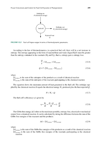
Enthalpy in
H (chemical energy)
Enthalpy out
Fuel cell
W e (electrical energy)
Rejected heat
Q
FIGURE 12.5 Fuel cell input–output in terms of thermodynamic parameters.
According to the law of thermodynamics, in a practical fuel cell, there will be a net increase in
entropy. The entropy appearing in the form of rejected heat and water (liquid H O) must be greater
2
than the entropy contained in the reactants (H and O ), that is, entropy gain ≥ entropy loss:
2
2
Q + Σ S products ≥ Σ (12.5)
T S reactants
Q ≥ T ⋅(Σ S reactants − Σ S products) (12.6)
where
∑S products is the sum of the entropies of the products as a result of chemical reaction
∑S reactants is the sum of the entropies of the reactants participating in the chemical reaction
The equation shows the minimum amount of heat generated in the fuel cell. The enthalpy sup-
plied by the chemical reaction H equals the electrical energy W produced plus the heat rejected Q:
e
H = W e + Q (12.7)
The fuel cell’s efficiency η is given by
−
HQ Q
η = W e = =− (12.8)
1
H H H
The Gibbs free energy ΔG refers to the maximum possible, entropy-free, electrical or mechanical
output from a chemical reaction. It can be calculated by taking the difference between the sum of the
Gibbs free energies of the reactants and the products:
∆G = ΣG products − ΣG reactants (12.9)
where
∑G products is the sum of the Gibbs free energies of the products as a result of the chemical reaction
∑G reactants is the sum of the Gibbs free energies of the reactants participating in the chemical
reaction