
Page 400 - Renewable Energy Devices and System with Simulations in MATLAB and ANSYS
P. 400
Microgrid for High-Surety Power: Architectures, Controls, Protection, and Demonstration 387
[10.00 ms/div]
i o 40 A/div
0
19 V u o 10 V/div
3.5 ms
(a)
[10.00 ms/div]
i o 40 A/div
0
20 V
4 ms u o 10 V/div
(b)
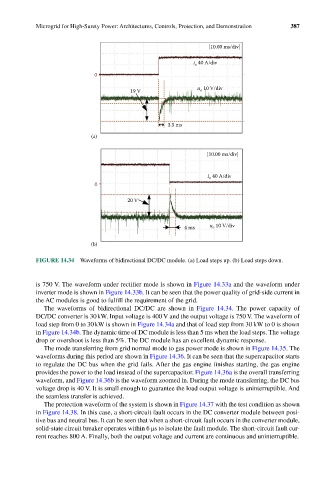
FIGURE 14.34 Waveforms of bidirectional DC/DC module. (a) Load steps up. (b) Load steps down.
is 750 V. The waveform under rectifier mode is shown in Figure 14.33a and the waveform under
inverter mode is shown in Figure 14.33b. It can be seen that the power quality of grid-side current in
the AC modules is good to fulfill the requirement of the grid.
The waveforms of bidirectional DC/DC are shown in Figure 14.34. The power capacity of
DC/DC converter is 30 kW. Input voltage is 400 V and the output voltage is 750 V. The waveform of
load step from 0 to 30 kW is shown in Figure 14.34a and that of load step from 30 kW to 0 is shown
in Figure 14.34b. The dynamic time of DC module is less than 5 ms when the load steps. The voltage
drop or overshoot is less than 5%. The DC module has an excellent dynamic response.
The mode transferring from grid normal mode to gas power mode is shown in Figure 14.35. The
waveforms during this period are shown in Figure 14.36. It can be seen that the supercapacitor starts
to regulate the DC bus when the grid fails. After the gas engine finishes starting, the gas engine
provides the power to the load instead of the supercapacitor. Figure 14.36a is the overall transferring
waveform, and Figure 14.36b is the waveform zoomed in. During the mode transferring, the DC bus
voltage drop is 40 V. It is small enough to guarantee the load output voltage is uninterruptible. And
the seamless transfer is achieved.
The protection waveform of the system is shown in Figure 14.37 with the test condition as shown
in Figure 14.38. In this case, a short-circuit fault occurs in the DC converter module between posi-
tive bus and neutral bus. It can be seen that when a short-circuit fault occurs in the converter module,
solid-state circuit breaker operates within 6 μs to isolate the fault module. The short-circuit fault cur-
rent reaches 800 A. Finally, both the output voltage and current are continuous and uninterruptible.