
Page 395 - Renewable Energy Devices and System with Simulations in MATLAB and ANSYS
P. 395
382 Renewable Energy Devices and Systems with Simulations in MATLAB and ANSYS ®
®
Control Fault Control Fault
Driver Driver
G G
DC/DC or DC/AC +
module C E E C
U 1
MOV
0 DC
bus
U 2 MOV
– C E E C
G G Detection unit
Driver Driver Driver unit
Control Fault Control Fault
Fault
Protect signal signal
Control
signal
Enable signal Control unit
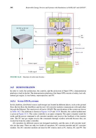
FIGURE 14.26 Structure of solid-state breaker.
14.5 DEMONSTRATION
In order to verify the architecture, the controls, and the protection of Super UPS, a demonstration
platform is built in the lab. The demonstration platform of the Super UPS consists of utility, fuel cell,
natural gas engine, Li-ion battery, supercapacitor, and PV.
14.5.1 Super UPS Platform
In this platform, distributed sources and storages are located in different places, such as the ground
floor, the first floor, the third floor, and the roof. All converter modules communicate with each other
through the Ethernet. The rated power of load is 100 kW. The specifications of the system are shown
in Table 14.3. The platform is shown in Figures 14.29 and 14.30. Besides, the control architecture
is given in Figure 14.31. The center controller is an upper computer. The upper computer sends the
mode and the power command to all converter modules and receives the feedback of the module
state. The FC and gas engine receive the commands through wireless network because they are
located far from the center controller.
All converters for different sources are designed modularly, and the sizes of all converter mod-
ules are the same. There are only two kinds of converters, DC converter module and AC converter
module. The DC converter modules are used for DC sources such as FC, battery, SC, and PV. The