
Page 392 - Renewable Energy Devices and System with Simulations in MATLAB and ANSYS
P. 392
Microgrid for High-Surety Power: Architectures, Controls, Protection, and Demonstration 379
TABLE 14.2
Specifications of Short-Circuit Analysis
Parameter Value
375 V
Positive/negative bus voltage V DC
10 mF
DC bus capacitor C DC
1 μH
Line impedance from bus capacitor to submodule L s
Short-circuit resistor of submodule R s 40 mΩ
100 kW
Rated power of submodule P r
133 A
Rated current of submodule I r
800
710
600
DC bus voltage (V) 400
200
0
0 0.05 0.2 0.4 0.6 0.8 1
(a) t (ms)
20 k
15 k
Fault current (A) 12 k
10 k
5 k
0
0 0.05 0.2 0.4 0.6 0.8 1
(b) t (ms)
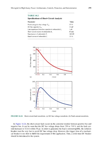
FIGURE 14.24 Short-circuit fault waveform. (a) DC bus voltage waveform. (b) Fault current waveform.
In Figure 14.24, the short-circuit fault occurs in the converter module between positive bus and
negative bus. It can be seen that the DC bus voltage drops from 750 to 710 V, and the fault cur-
rent increases to 12 kA within 50 μs. In order to guarantee the load is uninterruptible, the isolation
breaker must be very fast to avoid DC bus voltage drop. However, the trigger time of a mechani-
cal breaker is too slow to fulfill the requirement of this application. Thus, a solid-state DC breaker
should be introduced to the system.