
Page 387 - Renewable Energy Devices and System with Simulations in MATLAB and ANSYS
P. 387
374 Renewable Energy Devices and Systems with Simulations in MATLAB and ANSYS ®
®
loop is used to extract the high-frequency components of the load current. The high-frequency com-
ponents i p_dec and i n_dec are extracted from the inverter DC side current i invp and i invn by a band pass
filter. The SC voltage loop is used to maintain the supercapacitor voltage in a constant level. It
ensures that the supercapacitor has an enough margin to absorb or supply the power when the next
load jumping comes. The inner current loop is used for current reference tracking. Its reference
values i p_ref and i n_ref are obtained by the difference of the detection current (i p_dec and i n_dec ) and the
SC voltage loop output. The feedback output currents i and i of the DC–DC are sampled and
bn
bp
their switching frequency ripple is eliminated by the low-pass filter (LPF). And the proportional and
integral (PI) controller is utilized in the inner current loop control.
The lifetime of FC in cold backup is much longer than hot backup mode. Therefore, the FC oper-
ates in the cold backup mode if both utility and gas engine are normal. The cold start-up strategy for
FC is similar to that for gas engine, which will be discussed in the next part.
14.3.2.2 Gas Engine Unit Power Management
In order to improve the reliability of the gas engine unit, the cold backup strategy is applied.
Otherwise, the failure rate of gas engine will obviously increase in hot backup mode because of the
mechanical abrasion and aging. The cold start-up time of gas engine is long. Taking a 50 kW gas
engine as an example, 8.5 s is needed for gas engine cold start-up. Besides, the gas engine must start
without loads during this time. Thus, the supercapacitor is introduced to regulate the DC bus before
the gas engine finishes starting.
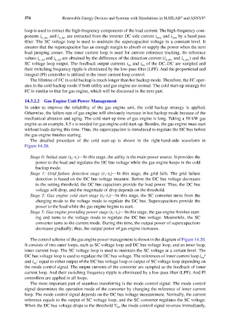
The detailed procedure of the cold start-up is shown in the right-hand-side waveform in
Figure 14.20.
Stage 0: Initial state (t –t )—In this stage, the utility is the main power source. It provides the
1
0
power to the load and regulates the DC bus voltage while the gas engine keeps in the cold
backup mode.
Stage 1: Grid failure detection stage (t –t )—In this stage, the grid fails. The grid failure
1
2
detection is based on the DC bus voltage measure. Before the DC bus voltage decreases
to the setting threshold, the DC bus capacitors provide the load power. Thus, the DC bus
voltage will drop, and the magnitude of drop depends on the threshold.
Stage 2: Gas engine cold start stage (t –t )—In this stage, the SC converter turns from the
3
2
charging mode to the voltage mode to regulate the DC bus. Supercapacitors provide the
power to the load while the gas engine begins to start.
Stage 3: Gas engine providing power stage (t –t )—In this stage, the gas engine finishes start-
4
3
ing and turns to the voltage mode to regulate the DC bus voltage. Meanwhile, the SC
converter turns to the current mode. During this time, the output power of supercapacitors
decreases gradually; thus, the output power of gas engine increases.
The control scheme of the gas engine power management is shown in the diagram of Figure 14.20.
It consists of two outer loops, such as SC voltage loop and DC bus voltage loop, and an inner loop,
inner current loop. The SC voltage loop is used to maintain the SC voltage at a certain level. The
DC bus voltage loop is used to regulate the DC bus voltage. The references of inner current loop i ref +
and i ref − equal to either output of the DC bus voltage loop or output of SC voltage loop depending on
the mode control signal. The output currents of the converter are sampled as the feedback of inner
current loop. And their switching frequency ripple is eliminated by a low-pass filter (LPF). And PI
controllers are applied in all loops.
The most important part of seamless transferring is the mode control signal. The mode control
signal determines the operation mode of the converter by changing the reference of inner current
loop. The mode control signal depends on the DC bus voltage measurement. Normally, the current
reference equals to the output of SC voltage loop, and the SC converter regulates the SC voltage.
When the DC bus voltage drops to the threshold V , the mode control signal reverses immediately,
th