Page 388 - Renewable Energy Devices and System with Simulations in MATLAB and ANSYS
P. 388

Microgrid for High-Surety Power: Architectures, Controls, Protection, and Demonstration  375


                               t         t          t         t          t


                               t 3       t 3        t 3       t 3        t 3


                               t 2       t 2        t 2       t 2        t 2
                               t 1       t 1        t 1       t 1        t 1

                               0         0          0         0          0
                        V DC  V th  P grid  P SC       P gas     P bus


                                                            v DC –  –  – v DC +  v DC +  v DC –
                                                          v dcref /2  +  v dcref /2  +  +  +  V th
                                              Supcap volt.   control  v scref  PI  PI  Bus voltage control  –  +  Reset signal   from controller


                                                 v  – sc +  +  i vdc –  i vdc +  Loop switch logic
                                                         PI
                                      Supercap   v sc –  –  +  PI  0  1  i cha +  0  1  S  R
                         Load                        v scref  i cha –  –  –  Q

                                     L sc         L sc
                                                           + i ref –
                                                       LPF      i ref +  Mode control  signal
                                                           –    +
                          Inverter           P sc      LPF     –
                                                            PI
                                                                 PI
                                                            d – PWM
                               DC bus                     PWM   d +

                        –
                  Bypass   +  V DC


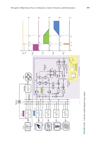
                                    P gas                                             Cold start control diagram of gas engine.


                       P grid


                                    Gas engine  Fuel cell  Li-ion battery  PV panel
                         Grid                    H 2  O 2                             FIGURE 14.20
   383   384   385   386   387   388   389   390   391   392   393