
Page 389 - Renewable Energy Devices and System with Simulations in MATLAB and ANSYS
P. 389
376 Renewable Energy Devices and Systems with Simulations in MATLAB and ANSYS ®
®
and then the current reference equals to the output of DC bus voltage loop. And the SC converter
regulates the DC bus voltage. The state of the mode control signal will be locked by an RS latch.
Only after the gas engine finishes starting, the mode control signal is reset by a reset signal from the
controller of the converter for gas engine. Then, the current reference will be equal to the output of
SC voltage loop again. And the SC converter regulates the SC voltage. Finally, the seamless trans-
ferring finishes.
14.4 PROTECTION
The protection is a key issue regarding the reliability for microgrid. Super UPS is required to have
an ability to handle the short-circuit faults of modules. In this section, the short-circuit fault current
is analyzed first, and then the design of the DC breaker is explained.
14.4.1 Short-Circuit Fault Current Analysis
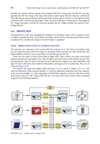
All converters are connected to the common DC bus in Figure 14.21. The short-circuit fault in any
one can lead to the drop of DC bus voltage. So no matter which converter has short-circuit fault, the
fault should be isolated as soon as possible to avoid affecting the DC bus.
There are four types of short-circuit fault in Super UPS: Type I fault is the short-circuit fault
between positive bus and negative bus. Type II fault is the short-circuit fault between positive bus
and neutral bus. Type III fault is the short-circuit fault between negative bus and neutral bus, and
Type IV fault is the short-circuit fault of both positive and negative bus to neutral bus. They are all
shown in Figure 14.22.
For instance, the equivalent failure model of Figure 14.22a is given in Figure 14.23. R is the
s
short-circuit resistor of the converter module. L is the line inductance impedance from bus capacitor
s
to the converter module. C is the capacitance of half DC bus capacitors. And i(t) is the short-circuit
DC
fault current, and u(t) is the voltage of the DC bus. The short-circuit fault current can be calculated
as given in the following equation:
Load
Grid
Switch
Switch
Fault current
Gas engine Failure module Battery
Switch Switch
Switch Switch
PV panel Fuel cell
Switch Switch H 2
O 2
Switch Switch
FIGURE 14.21 Module fault in a Super UPS.