
Page 385 - Renewable Energy Devices and System with Simulations in MATLAB and ANSYS
P. 385
372 Renewable Energy Devices and Systems with Simulations in MATLAB and ANSYS ®
®
Grid Load
Gas engine Battery
PV panel Fuel cell
H 2
O 2
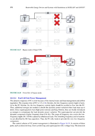
FIGURE 14.17 Bypass mode of Super UPS.
Grid Load
Gas engine Battery
PV panel
Fuel cell
H 2
O 2
FIGURE 14.18 Power flow of bypass mode.
14.3.2.1 Fuel Cell Unit Power Management
The dynamic response of FC is slow because of the internal water and heat management and airflow
regulation. The response time of FC is 1.9 s [14]. Besides, the low-frequency current ripple is harm-
ful to the FC lifetime. So, the low-frequency current ripple should be avoided to flow into the FC.
Thus, additional storages are needed to absorb the dynamic power variation when load steps up or
down. Since supercapacitors have high power density and long lifetime, they are finally introduced
as storages to compensate the load dynamic power variation. The supercapacitor can provide the
dynamic component (higher frequency than 0.16 Hz). The range of frequency also covers the low-
frequency ripple (50–150 Hz) caused by unbalanced loads. The switching frequency and its harmon-
ics are absorbed by DC bus capacitors. Thus, the FC only needs to provide the very low-frequency
component.
The control scheme of FC power management is illustrated in Figure 14.19. It consists of three
parts, such as detection loop, inner current loop, and supercapacitor (SC) voltage loop. The detection