
Page 380 - Renewable Energy Devices and System with Simulations in MATLAB and ANSYS
P. 380
Microgrid for High-Surety Power: Architectures, Controls, Protection, and Demonstration 367
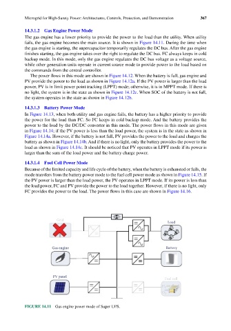
14.3.1.2 Gas Engine Power Mode
The gas engine has a lower priority to provide the power to the load than the utility. When utility
fails, the gas engine becomes the main source. It is shown in Figure 14.11. During the time when
the gas engine is starting, the supercapacitor temporarily regulates the DC bus. After the gas engine
finishes starting, the gas engine takes over the right to regulate the DC bus. FC always keeps in cold
backup mode. In this mode, only the gas engine regulates the DC bus voltage as a voltage source,
while other generation units operate in current source mode to provide power to the load based on
the commands from the central controller.
The power flows in this mode are shown in Figure 14.12. When the battery is full, gas engine and
PV provide the power to the load as shown in Figure 14.12a. If the PV power is larger than the load
power, PV is in limit power point tracking (LPPT) mode; otherwise, it is in MPPT mode. If there is
no light, the system is in the state as shown in Figure 14.12c. When SOC of the battery is not full,
the system operates in the state as shown in Figure 14.12b.
14.3.1.3 Battery Power Mode
In Figure 14.13, when both utility and gas engine fails, the battery has a higher priority to provide
the power for the load than FC. So FC keeps in cold backup mode. And the battery provides the
power to the load by the DC/DC converter in this mode. The power flows in this mode are given
in Figure 14.14; if the PV power is less than the load power, the system is in the state as shown in
Figure 14.14a. However, if the battery is not full, PV provides the power to the load and charges the
battery as shown in Figure 14.14b. And if there is no light, only the battery provides the power to the
load as shown in Figure 14.14c. It should be noticed that PV operates in LPPT mode if its power is
larger than the sum of the load power and the battery charge power.
14.3.1.4 Fuel Cell Power Mode
Because of the limited capacity and life cycle of the battery, when the battery is exhausted or fails, the
mode transfers from the battery power mode to the fuel cell power mode as shown in Figure 14.15. If
the PV power is larger than the load power, the PV operates in LPPT mode. If its power is less than
the load power, FC and PV provide the power to the load together. However, if there is no light, only
FC provides the power to the load. The power flows in this case are shown in Figure 14.16.
Grid
Load
Gas engine Battery
PV panel
Fuel cell
H 2
O 2
FIGURE 14.11 Gas engine power mode of Super UPS.