
Page 378 - Renewable Energy Devices and System with Simulations in MATLAB and ANSYS
P. 378
Microgrid for High-Surety Power: Architectures, Controls, Protection, and Demonstration 365
Grid C DC1 C DC1 Load
Load
C C
DC2 DC2
Gas engine C DC1
C DC2
Li-ion
battery L s1 L s1 PV
S s1 S s2 C s1 C s1 S s2 S s1
S S
L S s4 C C s4 S s3 L
s2 s3 s2 s2 s2
Supercapacitor L s1 L s1 Fuel cell
S s1 S C C s1 S S
s2 s1 s2 s1 H 2
L s2 S s3 S s4 C s2 C s2 S s4 S s3 L s2 O 2
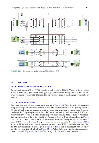
FIGURE 14.8 The power conversion system (PCS) of Super UPS.
14.3 CONTROL
14.3.1 Operation Modes of Super UPS
The target of control of Super UPS is to achieve high reliability [15–23]. There are five operation
modes in Super UPS, grid normal mode, gas engine power mode, battery power mode, fuel cell
power mode, and bypass mode. The mode that the system operates in is determined by the states of
sources.
14.3.1.1 Grid Normal Mode
The power distribution in grid normal mode is shown in Figure 14.9. When the utility is normal, the
utility provides power for load as the main source. The rectifier connected to the grid regulates the
DC bus, while all other converters connected to various sources operate in current control mode or
standby mode. The gas engine and fuel cell (FC) are in cold backup mode to extend their lifetime.
Photovoltaic (PV) operates in either maximum power point tracking (MPPT) mode or power lim-
iting state according to the system condition. The power flows in this mode are shown in Figure
14.10. When the state of charge (SOC) of the battery is full, the battery operates in float charge
mode. If PV power is less than load power, the system is in the state shown in Figure 14.10a,
where the PV and utility work together to supply power to load. If PV power is larger than utility,
the extra power is injected to grid as given in Figure 14.10c. If there is no sunlight, only the utility
provides the power to the load only as Figure 14.10e. When the battery is not full, the system is in
states as shown in Figure 14.10b, d, and f according to the PV and the load condition.