
Page 382 - Renewable Energy Devices and System with Simulations in MATLAB and ANSYS
P. 382
Microgrid for High-Surety Power: Architectures, Controls, Protection, and Demonstration 369
Grid Load
Gas engine Battery
PV panel Fuel cell
H 2
O 2
(d)
FIGURE 14.12 (Continued) Power flows of gas engine power mode.
Grid
Load
Gas engine Battery
PV panel
Fuel cell
H 2
O 2
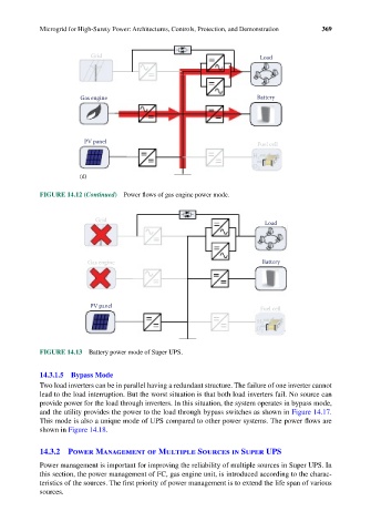
FIGURE 14.13 Battery power mode of Super UPS.
14.3.1.5 Bypass Mode
Two load inverters can be in parallel having a redundant structure. The failure of one inverter cannot
lead to the load interruption. But the worst situation is that both load inverters fail. No source can
provide power for the load through inverters. In this situation, the system operates in bypass mode,
and the utility provides the power to the load through bypass switches as shown in Figure 14.17.
This mode is also a unique mode of UPS compared to other power systems. The power flows are
shown in Figure 14.18.
14.3.2 Power Management of Multiple Sources in Super UPS
Power management is important for improving the reliability of multiple sources in Super UPS. In
this section, the power management of FC, gas engine unit, is introduced according to the charac-
teristics of the sources. The first priority of power management is to extend the life span of various
sources.