
Page 158 - Reservoir Geomechanics
P. 158
141 Faults and fractures at depth
Shmin SHmax
m = 0.6
t
s hmin
s hmin s Hmax
a. Mode I
Shmin SHmax T B
t b P
2b s hmin
s
s hmin v
b. Normal s v
Shmin SHmax T
P
t SS/RF X B
SS/NF
SS
2b
s hmin s s Hmax
v
c. Strike-slip
Shmin SHmax
B P
t
s Hmax
T
2b
s
s s Hmax v
d. Reverse v
Map view Stereonet Mohr circle Cross-section Focal mechanism
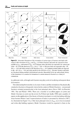
Figure 5.1. Schematic illustration of the orientation of various types of fractures and faults with
respect to the orientation of S Hmax and S hmin . (a) Mode I fractures and joints are expected to form
parallel to S Hmax and normal to S hmin . (b) Conjugate strike-slip faults are expected to be vertical and
◦
strike ∼30 from the direction of S Hmax (for µ ∼ 0.6). (c) Reverse faults are expected to dip ∼30 ◦
(for µ ∼ 0.6) and strike normal to the direction of S Hmax . (d) Conjugate normal faults are expected
◦
to dip ∼60 (for µ ∼ 0.6) and strike parallel to the direction of S Hmax . Because fractures and faults
are introduced during multiple deformational episodes (depending on the age and geologic history
of the formation) it is common for formations to contain numerous fractures at a variety of
orientations.
in carbonate rocks, although such features may play a role in localizing subsequent shear
deformation.
The relationship between the in situ state of stress and the orientation of hydraulically
conductivefracturesisfrequentlyviewedinthecontextofModeIfractures–extensional
fractures oriented perpendicular to the least principal stress (Secor 1965;du Rouchet
1981; Nur and Walder 1990). There are a number of excellent papers on joints and
Mode I fractures in rock (see the review by Pollard and Aydin 1988) and a number of
papers on the application of the theory of fracture mechanics to rock (including utilizing
shear fracture Modes 2 and 3 representations of faults) is presented by Atkinson (1987).
As illustrated in Figure 5.1a, if the least principal stress is S hmin (as is true in normal
and strike-slip faulting regimes), Mode I fractures would be expected to form in the