
Page 194 - Reservoir Geomechanics
P. 194
a. b.
N E S W N N E S W N
c.
0
W BO
270 90
180
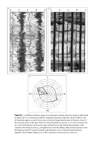
Figure 6.4. (a) Wellbore breakouts appear in an ultrasonic borehole televiewer image as dark bands
on either side of a well because of the low-amplitude ultrasonic reflections off the wellbore wall.
(b) Breakouts appear as out-of-focus areas in electrical image data because of the poor contact of
the electrode arrays on the pads of the tool where breakouts are present. (c) A cross-sectional view
of a well with breakouts can be easily made with televiewer data making determination of the
azimuth of the breakouts and w BO straightforward. Note the drilling-induced tensile fracture in the
left image located 90 from the azimuth of the breakouts, just as expected from the Kirsch
◦
equations. From Zoback, Barton et al.(2003). Reprinted with permission of Elsevier.