
Page 115 - Robot Builder's Bonanza
P. 115
84 BUILD A MOTORIZED WOODEN PLATFORM
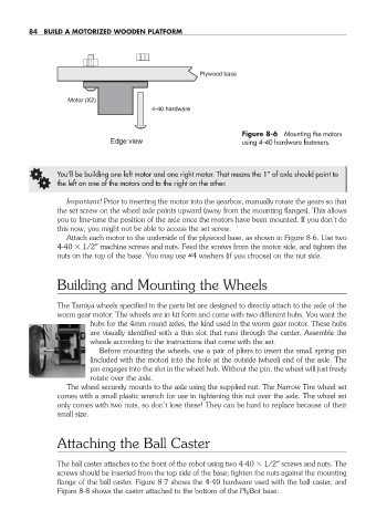
Plywood base
Motor (X2)
4-40 hardware
Figure 8-6 Mounting the motors
Edge view using 4-40 hardware fasteners.
G You’ll be building one left motor and one right motor. That means the 1″ of axle should point to
the left on one of the motors and to the right on the other.
Important! Prior to inserting the motor into the gearbox, manually rotate the gears so that
the set screw on the wheel axle points upward (away from the mounting flanges). This allows
you to fine- tune the position of the axle once the motors have been mounted. If you don’t do
this now, you might not be able to access the set screw.
Attach each motor to the underside of the plywood base, as shown in Figure 8-6. Use two
4-40 1/2″ machine screws and nuts. Feed the screws from the motor side, and tighten the
nuts on the top of the base. You may use #4 washers (if you choose) on the nut side.
Building and Mounting the Wheels
The Tamiya wheels specified in the parts list are designed to directly attach to the axle of the
worm gear motor. The wheels are in kit form and come with two different hubs. You want the
hubs for the 4mm round axles, the kind used in the worm gear motor. These hubs
are visually identified with a thin slot that runs through the center. Assemble the
wheels according to the instructions that come with the set.
Before mounting the wheels, use a pair of pliers to insert the small spring pin
(included with the motor) into the hole at the outside (wheel) end of the axle. The
pin engages into the slot in the wheel hub. Without the pin, the wheel will just freely
rotate over the axle.
The wheel securely mounts to the axle using the supplied nut. The Narrow Tire wheel set
comes with a small plastic wrench for use in tightening this nut over the axle. The wheel set
only comes with two nuts, so don’t lose these! They can be hard to replace because of their
small size.
Attaching the Ball Caster
The ball caster attaches to the front of the robot using two 4-40 1/2″ screws and nuts. The
screws should be inserted from the top side of the base; tighten the nuts against the mounting
flange of the ball caster. Figure 8-7 shows the 4-40 hardware used with the ball caster, and
Figure 8-8 shows the caster attached to the bottom of the PlyBot base.
08-chapter-8.indd 84 4/21/11 11:44 AM