
Page 114 - Robot Builder's Bonanza
P. 114
BUILDING AND ATTACHING THE MOTORS 83
1/2"
Gearbox case
1"
2"
Leave about 1"
Wheel axle
Nut with
setscrew
1-1/8"
1-3/8"
Left motor Right motor
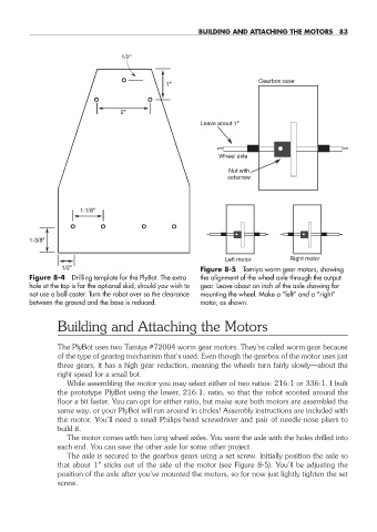
1/2" Figure 8-5 Tamiya worm gear motors, showing
Figure 8-4 Drilling template for the PlyBot. The extra the alignment of the wheel axle through the output
hole at the top is for the optional skid, should you wish to gear. Leave about an inch of the axle showing for
not use a ball caster. Turn the robot over so the clearance mounting the wheel. Make a “left” and a “right”
between the ground and the base is reduced. motor, as shown.
Building and Attaching the Motors
The PlyBot uses two Tamiya #72004 worm gear motors. They’re called worm gear because
of the type of gearing mechanism that’s used. Even though the gearbox of the motor uses just
three gears, it has a high gear reduction, meaning the wheels turn fairly slowly— about the
right speed for a small bot.
While assembling the motor you may select either of two ratios: 216:1 or 336:1. I built
the prototype PlyBot using the lower, 216:1, ratio, so that the robot scooted around the
floor a bit faster. You can opt for either ratio, but make sure both motors are assembled the
same way, or your PlyBot will run around in circles! Assembly instructions are included with
the motor. You’ll need a small Philips- head screwdriver and pair of needle- nose pliers to
build it.
The motor comes with two long wheel axles. You want the axle with the holes drilled into
each end. You can save the other axle for some other project.
The axle is secured to the gearbox gears using a set screw. Initially position the axle so
that about 1″ sticks out of the side of the motor (see Figure 8-5). You’ll be adjusting the
position of the axle after you’ve mounted the motors, so for now just lightly tighten the set
screw.
08-chapter-8.indd 83 4/21/11 11:44 AM