
Page 187 - Robot Builder's Bonanza
P. 187
156 DRAFTING BOTS WITH COMPUTER- AIDED DESIGN
motors. Small circles with thin crosshair marks show where holes go, and the size of the cir-
cles indicates the approximate diameter of the holes.
To use the template, just print it out, then tape or transfer it to the material used for your
base. Use the same techniques detailed previously under “Creating Layouts by Hand.”
MAKING LAYOUTS WITH LOW- COST CAD PROGRAMS
Another way to produce layouts for your robot projects is with a computer- aided design
(CAD) program. CAD is like a vector graphics program, but it also combines mechanical draft-
ing features. The idea behind CAD is that not only can you draw a square, you can draw a
square that is precisely 1″ by 2″. Absolute measurements are stored with the CAD file and,
when used with the appropriate printer, produce highly accurate renditions of your drawings.
CAD programs are often referred to as 2D or 3D. A 2D CAD program can create a two-
dimensional drawing. The layout on the drawing has height and width, but no depth. This is the
G kind you use to produce layouts for cutting and drilling.
A 3D program can create a three- dimensional drawing that has height, width, and depth.
Most 3D CAD programs can “render” 3D shapes using complex lighting and shading options.
3D CAD is not required for producing basic robot layouts, but can be used to visualize or
document its construction.
AutoCad, from AutoDesk, is perhaps the best- known CAD program. As with most com-
mercial CAD software, AutoCad is frightfully expensive. If you’re a student, you may qualify
for a discount.
An alternative is a free or low- cost CAD program. Several are available for download from
the Internet. While they may not compare with high- end commercial products like AutoCad,
they are more than sufficient for our application.
A leader in low- cost but capable CAD programs is TurboCAD. It’s available in different
editions, with both low- end and high- end versions— pick the consumer- oriented Deluxe ver-
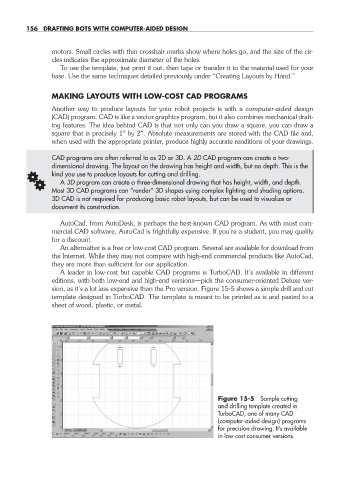
sion, as it’s a lot less expensive than the Pro version. Figure 15-5 shows a simple drill and cut
template designed in TurboCAD. The template is meant to be printed as is and pasted to a
sheet of wood, plastic, or metal.
Figure 15-5 Sample cutting
and drilling template created in
TurboCAD, one of many CAD
(computer- aided design) programs
for precision drawing. It’s available
in low- cost consumer versions.
15-chapter-15.indd 156 4/21/11 11:48 AM