
Page 235 - Robot Builder's Bonanza
P. 235
204 ROBOT POWER SYSTEMS
Current
limiting
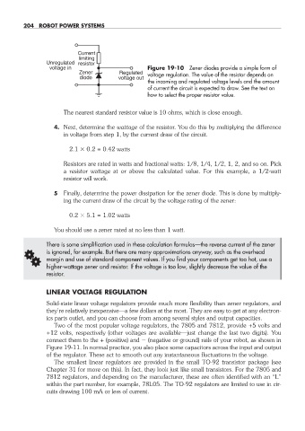
Unregulated resistor
voltage in Figure 19- 10 Zener diodes provide a simple form of
Zener Regulated voltage regulation. The value of the resistor depends on
diode voltage out
the incoming and regulated voltage levels and the amount
of current the circuit is expected to draw. See the text on
how to select the proper resistor value.
The nearest standard resistor value is 10 ohms, which is close enough.
4. Next, determine the wattage of the resistor. You do this by multiplying the difference
in voltage from step 1, by the current draw of the circuit.
2.1 0.2 = 0.42 watts
Resistors are rated in watts and fractional watts: 1/8, 1/4, 1/2, 1, 2, and so on. Pick
a resistor wattage at or above the calculated value. For this example, a 1/2- watt
resistor will work.
5 Finally, determine the power dissipation for the zener diode. This is done by multiply-
ing the current draw of the circuit by the voltage rating of the zener:
0.2 5.1 = 1.02 watts
You should use a zener rated at no less than 1 watt.
There is some simplification used in these calculation formulas— the reverse current of the zener
G is ignored, for example. But there are many approximations anyway, such as the overhead
margin and use of standard component values. If you find your components get too hot, use a
higher- wattage zener and resistor. If the voltage is too low, slightly decrease the value of the
resistor.
LINEAR VOLTAGE REGULATION
Solid- state linear voltage regulators provide much more flexibility than zener regulators, and
they’re relatively inexpensive— a few dollars at the most. They are easy to get at any electron-
ics parts outlet, and you can choose from among several styles and output capacities.
Two of the most popular voltage regulators, the 7805 and 7812, provide +5 volts and
+12 volts, respectively (other voltages are available— just change the last two digits). You
connect them to the + (positive) and (negative or ground) rails of your robot, as shown in
Fig ure 19- 11. In normal practice, you also place some capacitors across the input and output
of the regulator. These act to smooth out any instantaneous fluctuations in the voltage.
The smallest linear regulators are provided in the small TO- 92 transistor package (see
Chapter 31 for more on this). In fact, they look just like small transistors. For the 7805 and
7812 regulators, and depending on the manufacturer, these are often identified with an “L”
within the part number, for example, 78L05. The TO- 92 regulators are limited to use in cir-
cuits drawing 100 mA or less of current.
19-chapter-19.indd 204 4/21/11 11:49 AM