
Page 237 - Robot Builder's Bonanza
P. 237
206 ROBOT POWER SYSTEMS
Too, most linear regulators require a voltage source several volts higher than the expected
output voltage. The difference is called voltage drop, and it’s why you need at least 7 volts to
power a 5- volt circuit.
An alternative to linear regulators is the switching (or switching- mode) voltage regulator,
which is more expensive but more efficient. Most high- tech electronics equipment uses switch-
ing power supplies. They’re common and not frightfully expensive.
A good example of a step- down switching voltage regulator is the MAX738, from Maxim.
It comes in an 8- pin dual inline pin (DIP) IC package, among others; the DIP package is ideal
for homebrew circuits. With just a few added parts you can build a simple, compact, and effi-
cient voltage regulator. The output voltage is dependent on the external components that you
use. Refer to the datasheet for the MAX738 for sample circuits.
Some kinds of switching voltage regulators can increase a lower voltage to a higher one. These
are called step- up or boost regulators. One typical application is turning 3 volts from a pair of
G 1.5- volt alkaline cells into 5 volts, to run some microcontroller or other circuit. The Maxim
MAX756 is a good example of a step- up switching regulator, able to turn any voltage from 1 to
5 volts into a regulated 5- volt output. Pretty nifty.
USING MULTIPLE VOLTAGE REGULATION
Not every subsystem in your robot will require the same voltage. Some parts might use 3.3
volts, while others use 5 volts. This requires that you use separate regulators for each voltage.
Too, even if different subsystems require the same voltage, it’s not generally a good idea to
power them all from the same regulator. In many cases, it’s better to use multiple regulators.
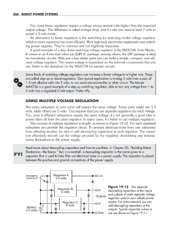
The concept of multiple regulation is simple, as shown in Figure 19- 12. For each regulated
subsystem you provide the regulator circuit. To prevent electrical noise from one subsystem
from affecting another, be sure to add decoupling capacitors at each regulator. The capaci-
tors effectively smooth out the voltage provided by the regulator, diminishing any instanta-
neous fluctuations in the power supply.
Read more about decoupling capacitors and how to use them, in Chapter 30, “Building Robot
Electronics— the Basics.” But, in a nutshell, a decoupling capacitor is the name given to a
FYI
capacitor that is used to help filter out electrical noise in a power supply. The capacitor is placed
between the positive and ground connections of the power supply.
Decoupling Regulator A 3.3V
capacitors 3.3 volts
Figure 19- 12 Use separate
Regulator B 5V decoupling capacitors at the inputs
5 volts
and outputs of each separate voltage
Outputs
regulator used in your robot’s power
Regulator C 9V system. For extra measure you can
9 volts add decoupling capacitors at the
Battery
(12 volts) outputs. Typical capacitor values to
Gnd use are shown in Figure 19- 11.
19-chapter-19.indd 206 4/21/11 11:49 AM