
Page 238 - Robot Builder's Bonanza
P. 238
DEALING WITH POWER BROWNOUTS 207
Dealing with Power Brownouts
You see, robots aren’t known to use power in an even, predictable manner. One moment the
robot’s sitting still, using very little power, waiting for the right time to pounce on your poor
unsuspecting cat. The next moment it’s screaming down the hall after the furry feline, burning
amps like they’re going out of style.
Every time the motors kick in, a high amount of current is drawn from the batteries. This
increase in current consumption can make the voltage delivered by the batteries momentarily
dip. If these same batteries also supply the electronics in your robot, a condition called brown-
out, or sag, could occur.
As the battery voltage drops below that needed for the regulator, the electronics go into a
brownout mode. They get enough power to stay on, but not enough for reliable operation. To
avoid possible brownouts:
• Use separate batteries for the electronics and the motors. This is the single best way to
avoid brownout problems. Use a small- capacity battery or pack for the electronics, and a
pack with larger AA, C, or D cells for the motors. Note: To make this work, the ground
leads of both battery supplies must be connected!
• Use batteries with a higher per- cell voltage, to ensure enough overhead for proper voltage
regulation. If you’re using NiCd or NiMH cells, for instance, which put out 1.2 volts per
cell, switch to rechargeable alkaline. These produce 1.5 volts per cell.
• Use one or more additional batteries to increase the voltage provided by the pack. Though
nonstandard— and sometimes a bit hard to find— use a five- cell battery pack with your
1.2- volt NiCd or NiMH batteries. That increases the pack voltage from 4.8 volts to 6 volts.
• Power the electronics from a single 9- volt battery. Use appropriate voltage regulation, of
course. The Arduino microcontroller boards have onboard regulation that will take the
9 volts input and provide the necessary 5 volts.
• Don’t let your batteries get so discharged that they can’t provide even the minimal operat-
ing current for your bot.
• Design for lower- voltage electronics. Some microcontrollers operate at 3.3 volts.
5 volts
5 3.3 k
3
resistor
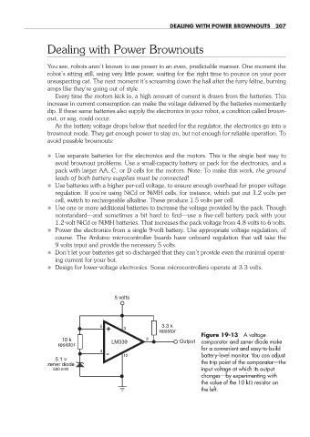
Figure 19- 13 A voltage
10 k 2 Output comparator and zener diode make
resistor LM339
for a convenient and easy- to- build
4
12 battery- level monitor. You can adjust
5.1 v
zener diode the trip point of the comparator— the
500 mW input voltage at which its output
changes— by experimenting with
the value of the 10 k resistor on
the left.
19-chapter-19.indd 207 4/21/11 11:49 AM