
Page 339 - Robot Builder's Bonanza
P. 339
308 BUILD ROBOTS WITH WHEELS AND TRACKS
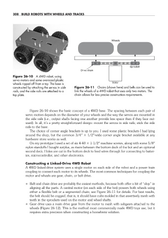
Wheels
Sprocket
Drive chain
Figure 26- 10 A 4WD robot, using
servo motors and some oversized plastic
wheels ripped off from a toy. The base is Motor
constructed by attaching the servos in side Figure 26- 11 Chains (shown here) and belts can be used to
rails, and the side rails are attached to a link the wheels of a 4WD robot that uses only two motors. The
top plate. chain allows for less precise construction requirements.
Figure 26- 10 shows the basic concept of a 4WD base. The spacing between each pair of
servo motors depends on the diameter of your wheels and the way the servos are mounted in
the side rails (i.e., output shafts facing one another provide less space than if they face out-
ward). In all, it’s a pretty straightforward design: mount the servos in side rails; stick the side
rails to the base.
The choice of corner angle brackets is up to you. I used some plastic brackets I had lying
around the shop, but the common 3/4″ 1/2″-wide corner angle bracket available at any
hardware store works as well.
On my prototype I used a set of six 4- 40 1- 1/2″ machine screws, along with some 5/8″
nylon standoffs I bought surplus, as risers between the bottom deck of the bot and an optional
second deck. Holes are cut in the bottom deck to feed wires through for connecting to batter-
ies, microcontroller, and other electronics.
Constructing a Linked- Drive 4WD Robot
A 4WD linked- drive system uses a single motor on each side of the robot and a power train
coupling to connect each motor to its wheels. The most common techniques for coupling the
motor and wheels are gear, chain, or belt drive.
• Belt and chain drive are probably the easiest methods, because both offer a bit of “slop” in
aligning all the parts. A central motor (on each side of the bot) powers both wheels using
either a flexible belt or a segmented chain; see Figure 26- 11 for details. For best results,
the belt should be cogged; that is, it should have nubs molded in that assertively mesh with
teeth in the sprockets used on the motor and wheel shafts.
• Gear drive uses a main drive gear from the motor to mesh with subgears attached to the
wheels (Figure 26- 12). This is the method most commercially made 4WD toys use, but it
requires extra precision when constructing a homebrew solution.
26-chapter-26.indd 308 4/21/11 11:52 AM