
Page 344 - Robot Builder's Bonanza
P. 344
BUILDING TANK- STYLE ROBOTS 313
1-1/8"
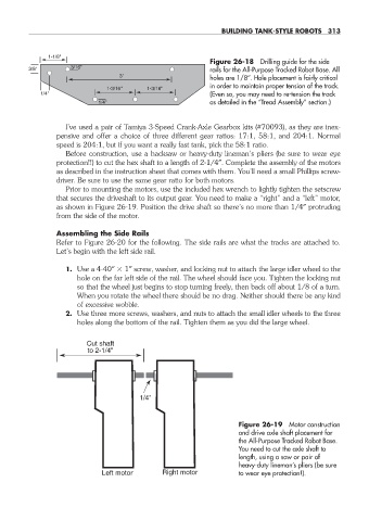
Figure 26- 18 Drilling guide for the side
3/16"
3/8" rails for the All- Purpose Tracked Robot Base. All
3" holes are 1/8″. Hole placement is fairly critical
in order to maintain proper tension of the track.
1-3/16" 1-3/16"
1/4" (Even so, you may need to re- tension the track
1/4" as detailed in the “Tread Assembly” section.)
I’ve used a pair of Tamiya 3- Speed Crank- Axle Gearbox kits (#70093), as they are inex-
pensive and offer a choice of three different gear ratios: 17:1, 58:1, and 204:1. Normal
speed is 204:1, but if you want a really fast tank, pick the 58:1 ratio.
Before construction, use a hacksaw or heavy- duty lineman’s pliers (be sure to wear eye
protection!!) to cut the hex shaft to a length of 2- 1/4″. Complete the assembly of the motors
as described in the instruction sheet that comes with them. You’ll need a small Phillips screw-
driver. Be sure to use the same gear ratio for both motors.
Prior to mounting the motors, use the included hex wrench to lightly tighten the setscrew
that secures the driveshaft to its output gear. You need to make a “right” and a “left” motor,
as shown in Figure 26- 19. Position the drive shaft so there’s no more than 1/4″ protruding
from the side of the motor.
Assembling the Side Rails
Refer to Figure 26- 20 for the following. The side rails are what the tracks are attached to.
Let’s begin with the left side rail.
1. Use a 4- 40″ 1″ screw, washer, and locking nut to attach the large idler wheel to the
hole on the far left side of the rail. The wheel should face you. Tighten the locking nut
so that the wheel just begins to stop turning freely, then back off about 1/8 of a turn.
When you rotate the wheel there should be no drag. Neither should there be any kind
of excessive wobble.
2. Use three more screws, washers, and nuts to attach the small idler wheels to the three
holes along the bottom of the rail. Tighten them as you did the large wheel.
Cut shaft
to 2-1/4"
1/4"
Figure 26- 19 Motor construction
and drive axle shaft placement for
the All- Purpose Tracked Robot Base.
You need to cut the axle shaft to
length, using a saw or pair of
heavy- duty lineman’s pliers (be sure
Left motor Right motor to wear eye protection!).
26-chapter-26.indd 313 4/21/11 11:52 AM