Page 345 - Robot Builder's Bonanza
P. 345

314    BUILD ROBOTS WITH WHEELS AND TRACKS
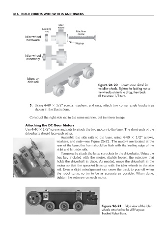

                                      Idler
                                     wheel
                            Locking
                              nut               Machine
                                                 screw
                   Idler wheel
                   hardware
                                               Washer


                   Idler wheel
                   assembly


                   Idlers on
                    side rail
                                                            Figure 26- 20  Construction detail for
                                                            the idler wheels. Tighten the locking nut so
                                                            the wheel just starts to drag, then back
                                                            off the screw 1/8 turn.


                     3.  Using 4- 40   1/2″ screws, washers, and nuts, attach two corner angle brackets as
                        shown in the illustrations.

                     Construct the right side rail in the same manner, but in mirror image.

                   Attaching the DC Gear Motors
                   Use 4- 40   1/2″ screws and nuts to attach the two motors to the base. The short ends of the
                   driveshafts should face each other.
                                       Assemble the side rails to the base, using 4- 40    1/2″ screws,
                                     washers, and  nuts— see Figure 26- 21. The motors are located at the
                                     rear of the base; the front should be flush with the leading edge of the
                                     right and left side rails.
                                       Temporarily attach the large sprockets to the driveshafts. Using the
                                     hex key included with the motor, slightly loosen the setscrew that
                                     holds the driveshaft in place. As needed, move the driveshaft in the
                                     motor so that the sprocket lines up with the idler wheels in the side
                                     rail. Even a slight misalignment can cause the track to pop off when
                                     the robot turns, so try to be as accurate as possible. When done,
                                     tighten the setscrew on each motor.


                                                              Figure 26- 21  Edge view of the idler
                                                              wheels attached to the  All- Purpose
                                                              Tracked Robot Base.


   26-chapter-26.indd   314                                                                      4/22/11   9:22 AM
   340   341   342   343   344   345   346   347   348   349   350