
Page 229 -
P. 229
212 Computed-Torque Control
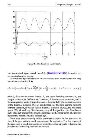
Figure 4.4.10: (Cont) (c) w n =50 rad/s.
robot controls designer to understand. See [Franklin et al. 1986] for a reference
on classical control theory.
A simplified dynamical model of a robot arm with electric actuators may
be written as (Section 3.6)
(4.4.52)
with J m the actuator motor inertia, B m the rotor damping constant, k m the
torque constant, k b the back emf constant, R the armature resistance, and r i
the gear ratio for joint i. The motor angle is denoted θ i (t). The constant portions
of the diagonal elements of M(q) are denoted m ii . The time-varying portions
of these elements, as well as the off-diagonal elements of M(q), the nonlinear
terms N(q, ), and any disturbances d are all lumped into the disturbance
d i (t). Thus d i (t) contains the effects on joint i of all the other joints. The control
input is the motor armature voltage v i (t).
Note that predominantly motor parameters appear in this equation. In
fact, if the gear ratio is small, even m ii may be neglected. For this reason, if
the gear ratio is small, the robot arm control problem virtually reduces to the
problem of controlling the actuator motors.
Copyright © 2004 by Marcel Dekker, Inc.