
Page 125 - Robot Builders Source Book - Gordon McComb
P. 125
114 Dynamic Analysis of Drives
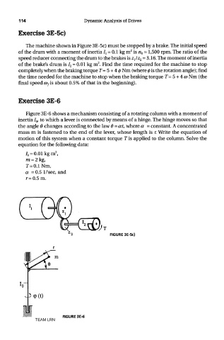
Exercise 3E-5c)
The machine shown in Figure 3E-5c) must be stopped by a brake. The initial speed
2
of the drum with a moment of inertia ^ = 0.1 kg m is n 0 = 1,500 rpm. The ratio of the
speed reducer connecting the drum to the brakes is zjz 2 = 3.16. The moment of inertia
2
of the brake's drum is I 2 = 0.01 kg m . Find the time required for the machine to stop
completely when the braking torque T= 5 + 4 0 Nm (where 0 is the rotation angle); find
the time needed for the machine to stop when the braking torque T= 5 + 4 a> Nm (the
final speed a> fis about 0.5% of that in the beginning).
Exercise 3E-6
Figure 3E-6 shows a mechanism consisting of a rotating column with a moment of
inertia I 0, to which a lever is connected by means of a hinge. The hinge moves so that
the angle 6 changes according to the law 6 = at, where a = constant. A concentrated
mass m is fastened to the end of the lever, whose length is r. Write the equation of
motion of this system when a constant torque T is applied to the column. Solve the
equation for the following data:
FIGURE 3E-5c)
FIGURE 3E-6
TEAM LRN