
Page 122 - Robot Builders Source Book - Gordon McComb
P. 122
Exercises 111
FIGURE 3E-3b)
Exercise 3E-4
The hydraulic cylinder shown in Figure 3E-4 is described by the following
parameters:
2
Pressure of the working liquid p = 500 N/cm ,
Force of resistance Q = 5000 N,
2
Cross-area of the piston = 50 cm ,
Moving mass M= 200 kg, and
2 2
Coefficient of hydraulic resistance \// = 150 Nsec /m .
Calculate the time needed to develop a piston speed V= 5 m/sec; Estimate the time
needed to obtain a displacement s = 0.1 m.
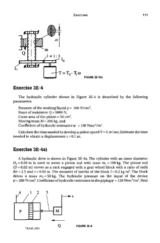
Exercise 3E-4a)
A hydraulic drive is shown in Figure 3E-4a. The cylinder with an inner diameter
D 0 = 0.08 m is used to move a piston rod with mass m l = 100 kg. The piston rod
(D = 0.02 m) serves as a rack engaged with a gear wheel block with a ratio of radii
2
R/r=2.5 and r= 0.04 m. The moment of inertia of the block /= 0.2 kg m . The block
drives a mass ra 2 = 50 kg. The hydraulic pressure on the input of the device
2
2
2
p = 200 N/cm . Coefficient of hydraulic resistance in the piping y = 120 Nsec /m . Find
FIGURE 3E-4
TEAM LRN