
Page 124 - Robot Builders Source Book - Gordon McComb
P. 124
Exercises 113
Calculate the time needed to lift the mass (for both cases separately) from the
moment in time that the valve 3 is actuated until the time the mass reaches point s max.
Exercise 3E-5a)
2
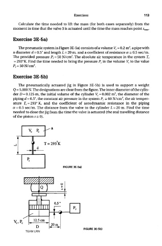
The pneumatic system in Figure 3E-5a) consists of a volume V c = 0.2 m , a pipe with
a diameter d = 0.5" and length L = 20 m, and a coefficient of resistance a = 0.5 sec/m.
2
The provided pressure P r= 50 N/cm . The absolute air temperature in the system T r
= 293° K. Find the time needed to bring the pressure P c in the volume V c to the value
2
P r = 50N/cm .
Exercise 3E-5b)
The pneumatically actuated jig in Figure 3E-5b) is used to support a weight
Q = 5,000 N. The designations are clear from the figure. The inner diameter of the cylin-
3
der D = 0.125 m, the initial volume of the cylinder V c = 0.002 m , the diameter of the
2
piping d = 0.5", the constant air pressure in the system P r = 60 N/cm , the air temper-
ature T c = 293° K, and the coefficient of aerodynamic resistance in the piping
a = 0.5 sec/m. The distance from the valve to the cylinder L = 20 m. Find the time
needed to close the jig from the time the valve is actuated (the real travelling distance
of the piston s = 0).
FIGURE 3E-5a)
FIGURE 3E-5b)
TEAM LRN