
Page 221 - Robot Builders Source Book - Gordon McComb
P. 221
6.2 Linear Transportation 209
liquid 2 (or gas, vapor, environment, etc.), which is contained in tank 3. Conveying
chain 4 is guided by rollers 5 and driven by sprocket 6. To compensate for possible
length changes in the chain, compensating roller 7, which can slide and is pulled by
load 8, is used. At position A the parts are loaded onto the chain (separately or in
baskets) while at position B they are unloaded. The length of the tanks and the speed
of the chain determine the time of treatment and the output of the device. Often, a
process requires several dippings (or other treatments). Then the conveying system
consists of more rollers 5 for lowering and lifting parts 1 during passage from one tank
(chamber, area zone, etc.) to the next and, of course, the chain is much longer. Atten-
tion must be paid to the fact that in this case a certain number of parts are always trav-
elling in the gaps between tanks. This entails:
• More parts loaded on the machine, thus greater masses to be moved;
• Greater time interval when the parts are not being treated and are in contact
with air.
In cases where these circumstances must be avoided, the arrangement shown in
Figure 6.5 can help. Here, a line of tanks 1 is served by a special conveyor system con-
sisting of horizontal transporting chain 2 and several vertical conveyors 3. The speed
of horizontal transportation V l is much slower than the speeds V 2 of the vertical con-
veyors. When the parts (baskets, blanks, etc.) are suspended on horizontal chain 2 in
region A they begin to move leftward at speed V 1 until they reach the first vertical chain
3, which catches hangers 4 and transfers them with speed V 2 (i.e., rapidly) into the first
tank, and returns the hangers to the horizontal conveyor. It is worthwhile to explain
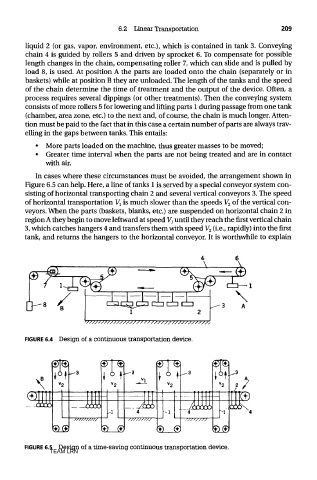
FIGURE 6.4 Design of a continuous transportation device.
FIGURE 6.5 Design of a time-saving continuous transportation device.
TEAM LRN