
Page 222 - Robot Builders Source Book - Gordon McComb
P. 222
210 Transporting Devices
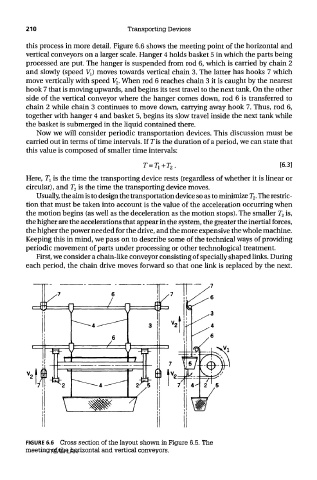
this process in more detail. Figure 6.6 shows the meeting point of the horizontal and
vertical conveyors on a larger scale. Hanger 4 holds basket 5 in which the parts being
processed are put. The hanger is suspended from rod 6, which is carried by chain 2
and slowly (speed VJ moves towards vertical chain 3. The latter has hooks 7 which
move vertically with speed V 2. When rod 6 reaches chain 3 it is caught by the nearest
hook 7 that is moving upwards, and begins its test travel to the next tank. On the other
side of the vertical conveyor where the hanger comes down, rod 6 is transferred to
chain 2 while chain 3 continues to move down, carrying away hook 7. Thus, rod 6,
together with hanger 4 and basket 5, begins its slow travel inside the next tank while
the basket is submerged in the liquid contained there.
Now we will consider periodic transportation devices. This discussion must be
carried out in terms of time intervals. If Tis the duration of a period, we can state that
this value is composed of smaller time intervals:
Here, T\ is the time the transporting device rests (regardless of whether it is linear or
circular), and T 2 is the time the transporting device moves.
Usually, the aim is to design the transportation device so as to minimize T 2. The restric-
tion that must be taken into account is the value of the acceleration occurring when
the motion begins (as well as the deceleration as the motion stops). The smaller T 2 is,
the higher are the accelerations that appear in the system, the greater the inertia! forces,
the higher the power needed for the drive, and the more expensive the whole machine.
Keeping this in mind, we pass on to describe some of the technical ways of providing
periodic movement of parts under processing or other technological treatment.
First, we consider a chain-like conveyor consisting of specially shaped links. During
each period, the chain drive moves forward so that one link is replaced by the next.
FIGURE 6.6 Cross section of the layout shown in Figure 6.5. The
meeting of the horizontal and vertical conveyors.
TEAM LRN