
Page 227 - Robot Builders Source Book - Gordon McComb
P. 227
6.2 Linear Transportation 215
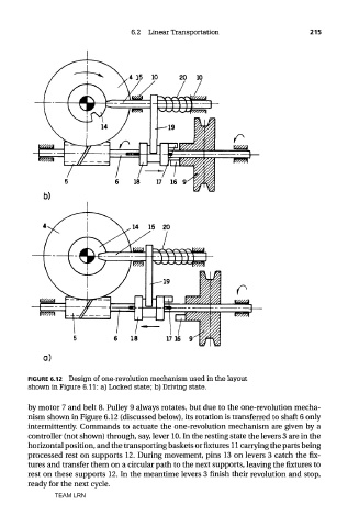
FIGURE 6.12 Design of one-revolution mechanism used in the layout
shown in Figure 6.11: a) Locked state; b) Driving state.
by motor 7 and belt 8. Pulley 9 always rotates, but due to the one-revolution mecha-
nism shown in Figure 6.12 (discussed below), its rotation is transferred to shaft 6 only
intermittently. Commands to actuate the one-revolution mechanism are given by a
controller (not shown) through, say, lever 10. In the resting state the levers 3 are in the
horizontal position, and the transporting baskets or fixtures 11 carrying the parts being
processed rest on supports 12. During movement, pins 13 on levers 3 catch the fix-
tures and transfer them on a circular path to the next supports, leaving the fixtures to
rest on these supports 12. In the meantime levers 3 finish their revolution and stop,
ready for the next cycle.
TEAM LRN